
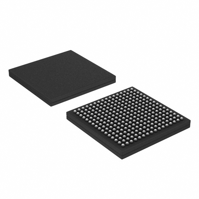

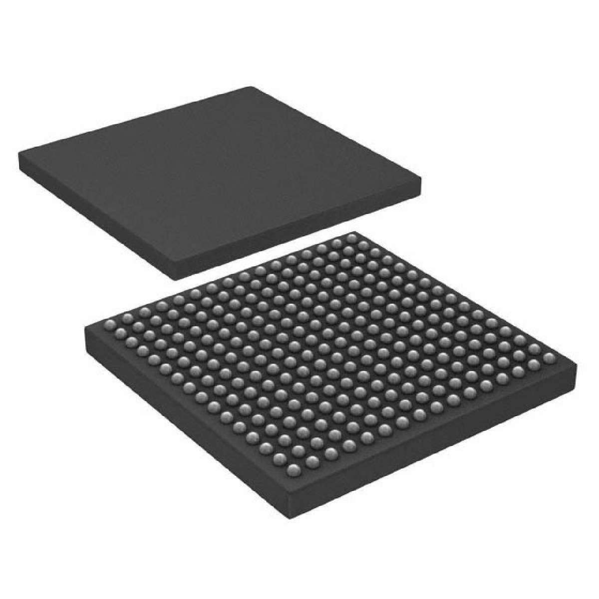
LPC4370 系列 204 MHz 282 kB RAM 双核 32 位 微控制器 - LBGA-256
Overview
The LPC4370 are ARM Cortex-M4 based microcontrollers for embedded applications which include an ARM Cortex-M0 coprocessor and an ARM Cortex-M0 subsystem for managing peripherals, 282 kB of SRAM, advanced configurable peripherals such as the State Configurable Timer SCT and the Serial General Purpose I/O SGPIO interface, two High-speed USB controllers, Ethernet, LCD, an external memory controller, and multiple digital and analog peripherals including a high-speed 12-bit ADC. The LPC4370 operate at CPU frequencies of up to 204 MHz.
The ARM Cortex-M4 is a next generation 32-bit core that offers system enhancements such as low power consumption, enhanced debug features, and a high level of support block integration. The ARM Cortex-M4 CPU incorporates a 3-stage pipeline, uses a Harvard architecture with separate local instruction and data buses as well as a third bus for peripherals, and includes an internal prefetch unit that supports speculative branching. The ARM Cortex-M4 supports single-cycle digital signal processing and SIMD instructions. A hardware floating-point processor is integrated in the core.
The LPC4370 include an application ARM Cortex-M0 coprocessor and a second ARM Cortex-M0 subsystem for managing the SGPIO and SPI peripherals. The ARM Cortex-M0 core is an energy-efficient and easy-to-use 32-bit core which is code- and tool-compatible with the Cortex-M4 core. Both Cortex-M0 cores offer up to 204 MHz performance with a simple instruction set and reduced code size.
MoreLess
## Features
* Main Cortex-M4 processor:
* ARM Cortex-M4 processor, running at frequencies of up to 204 MHz
* ARM Cortex-M4 built-in Memory Protection Unit MPU supporting eight regions
* ARM Cortex-M4 built-in Nested Vectored Interrupt Controller NVIC
* Hardware floating-point unit
* Non-maskable Interrupt NMI input
* JTAG and Serial Wire Debug SWD, serial trace, eight breakpoints, and four watch points
* Enhanced Trace Module ETM and Enhanced Trace Buffer ETB support
* System tick timer
* Cortex-M0 coprocessor:
* ARM Cortex-M0 coprocessor capable of off-loading the main ARM Cortex-M4 processor
* Running at frequencies of up to 204 MHz
* JTAG and built-in NVIC
* Cortex-M0 subsystem:
* ARM Cortex-M0 processor controlling the SPI and SGPIO peripherals residing on a separate AHB multilayer matrix with direct access to 2 kB + 16 kB of SRAM
* Running at frequencies of up to 204 MHz
* Connected via a core-to-core bridge to the main AHB multilayer matrix and the main ARM Cortex-M4 processor
* On-chip memory:
* 264 kB SRAM for code and data use on the main AHB multilayer matrix plus 18 kB of SRAM on the Cortex-M0 subsystem
* Multiple SRAM blocks with separate bus access. Two SRAM blocks can be powered down individually
* 64 kB ROM containing boot code and on-chip software drivers
* 64-bit + 256 bit general-purpose One-Time Programmable OTP memory
* Configurable digital peripherals:
* Serial GPIO SGPIO interface
* State Configurable Timer SCT subsystem on AHB
* Global Input Multiplexer Array GIMA allows to cross-connect multiple inputs and outputs to event driven peripherals like the timers, SCT, and ADC0/1
* Serial interfaces:
* Quad SPI Flash Interface SPIFI with four lanes and up to 52 MB per second
* 10/100T Ethernet MAC with RMII and MII interfaces and DMA support for high throughput at low CPU load. Support for IEEE 1588 time stamping/advanced time stamping IEEE 1588-2008 v2
* One High-speed USB 2.0 Host/Device/OTG interface with DMA support and on-chip high-speed PHY
* One High-speed USB 2.0 Host/Device interface with DMA support, on-chip full-speed PHY and ULPI interface to external high-speed PHY
* USB interface electrical test software included in ROM USB stack
* One 550 UART with DMA support and full modem interface
* Three 550 USARTs with DMA and synchronous mode support and a smart card interface conforming to ISO7816 specification. One USART with IrDA interface
* Two C_CAN 2.0B controllers with one channel each. Use of C_CAN controller excludes operation of all other peripherals connected to the same bus bridge
* Two SSP controllers with FIFO and multi-protocol support. Both SSPs with DMA support
* One SPI controller
* One Fast-mode Plus I²C-bus interface with monitor mode and open-drain I/O pins conforming to the full I²C-bus specification. Supports data rates of up to 1 Mbit/s
* One standard I²C-bus interface with monitor mode and with standard I/O pins
* Two I²S interfaces, each with DMA support and with one input and one output
* Digital peripherals:
* External Memory Controller EMC supporting external SRAM, ROM, NOR flash, and SDRAM devices
* LCD controller with DMA support and a programmable display resolution of up to 1024 H x 768 V. Supports monochrome and color STN panels and TFT color panels; supports 1/2/4/8 bpp Color Look-Up Table CLUT and 16/24-bit direct pixel mapping
* Secure Digital Input Output SD/MMC card interface
* Eight-channel General-Purpose DMA GPDMA controller can access all memories on the AHB and all DMA-capable AHB slaves
* 164 General-Purpose Input/Output GPIO pins with configurable pull-up/pull-down resistors and open-drain mode
* GPIO registers are located on the AHB for fast access. GPIO ports have DMA support
* Up to eight GPIO pins can be selected from all GPIO pins as edge and level sensitive interrupt sources
* Two GPIO group interrupt modules enable an interrupt based on a programmable pattern of input states of a group of GPIO pins
* Four general-purpose timer/counters with capture and match capabilities
* One motor control Pulse Width Modulator PWM for three-phase motor control
* One Quadrature Encoder Interface QEI
* Repetitive Interrupt timer RI timer
* Windowed watchdog timer WWDT
* Ultra-low power Real-Time Clock RTC on separate power domain with 256 bytes of battery powered backup registers
* Alarm timer; can be battery powered
* Analog peripherals:
* One 10-bit DAC with DMA support and a data conversion rate of 400 kSamples/s. LBGA256 package only
* Two 8-channel, 10-bit ADCs ADC0/1 with DMA support and a data conversion rate of 400 kSamples/s for a total of 16 independent channels. The 10-bit ADCs are only available on the LBGA256 package
* One 6-channel, 12-bit high-speed ADC ADCHS with DMA support and a data conversion rate of 80 MSamples/s
* Unique ID for each device
* Clock generation unit:
* Crystal oscillator with an operating range of 1 MHz to 25 MHz
* 12 MHz Internal RC IRC oscillator trimmed to 1 % accuracy over temperature and voltage
* Ultra-low power Real-Time Clock RTC crystal oscillator
* Three PLLs allow CPU operation up to the maximum CPU rate without the need for a high-frequency crystal. The second PLL is dedicated to the High-speed USB, the third PLL can be used as audio PLL
* Clock output
* Power:
* Single 3.3 V 2.2 V to 3.6 V power supply with on-chip DC-to-DC converter for the core supply and the RTC power domain
* RTC power domain can be powered separately by a 3 V battery supply
* Four reduced power modes: Sleep, Deep-sleep, Power-down, and Deep power-down
* Processor wake-up from Sleep mode via wake-up interrupts from various peripherals
* Wake-up from Deep-sleep, Power-down, and Deep power-down modes via external interrupts and interrupts generated by battery powered blocks in the RTC power domain
* Brownout detect with four separate thresholds for interrupt and forced reset
* Available as LBGA256 and TFBGA100 packages
## Target Applications
* Motor control
* Power management
* White goods
* RFID readers
* Embedded audio applications
* Industrial automation
* e-metering
## Features
频率 204 MHz
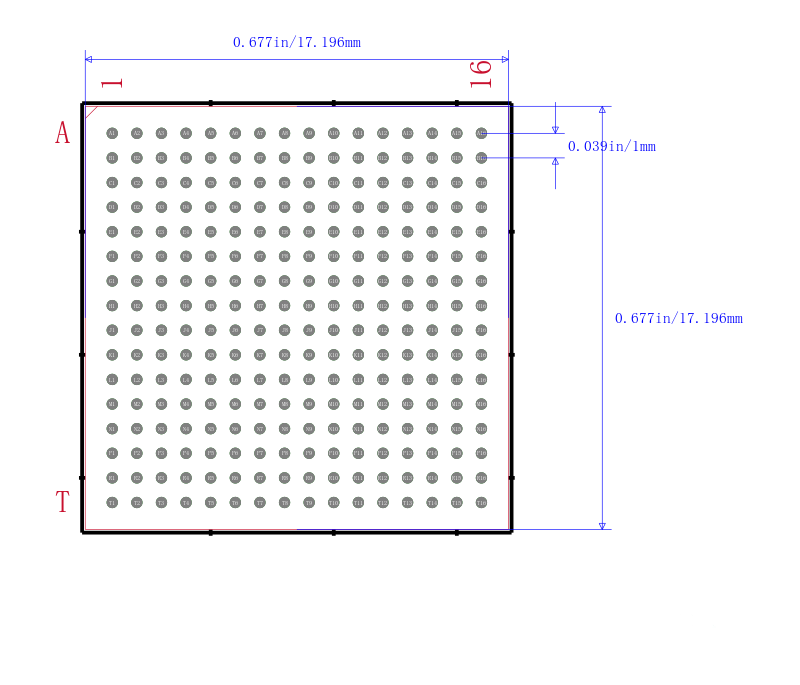
针脚数 256
RAM大小 282 KB
位数 32
FLASH内存容量 0 kB
模数转换数ADC 2
输入/输出数 164 Input
工作温度Max 85 ℃
工作温度Min -40 ℃
耗散功率Max 1500 mW
数模转换数DAC 1
电源电压 2.2V ~ 3.6V
电源电压Max 3.6 V
电源电压Min 2.2 V
安装方式 Surface Mount
引脚数 256
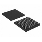
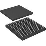
封装 LBGA-256
封装 LBGA-256
重量 740.5550414100001 mg
工作温度 -40℃ ~ 85℃
产品生命周期 Active
包装方式 Tray
制造应用 工业, 计量, 音频, 自动化与过程控制, 电机驱动与控制, 电源管理
RoHS标准 RoHS Compliant
含铅标准 Lead Free