


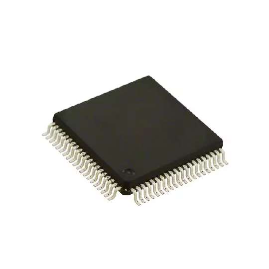
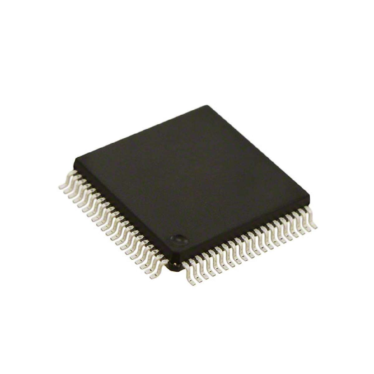
IC MCU 16Bit 64KB FLASH 80QFP
Introduction
Overview
The MC9S12E-Family is a 112/80 pin low cost general purpose MCU family. All members of the MC9S12E-Family are comprised of standard on-chip peripherals including a 16-bit central processing unit HCS12 CPU, up to 256K bytes of Flash EEPROM, up to 16K bytes of RAM, three asynchronous serial communications interface modules SCI, a serial peripheral interface SPI, an Inter-IC Bus IIC, three 4-channel 16-bit timer modules TIM, a 6-channel 15-bit Pulse Modulator with Fault protection module PMF, a 6-channel 8-bit Pulse Width Modulator PWM, a 16-channel 10-bit analog-to-digital converter ADC, and two 1-channel 8-bit digital-to-analog converters DAC. The MC9S12E-Family has full 16-bit data paths throughout. The inclusion of a PLL circuit allows power consumption and performance to be adjusted to suit operational requirements. In addition to the I/O ports available on each module, 16 dedicated I/O port bits are available with Wake-Up capability from STOP or WAIT mode. Furthermore, an on chip bandgap based voltage regulator VREG generates the internal digital supply voltage of 2.5V VDD from a 3.135V to 5.5V external supply range.
Features
• 16-bit HCS12 CORE
– HCS12 CPU
i. Upward compatible with M68HC11 instruction set
ii. Interrupt stacking and programmer’s model identical to M68HC11
iii. Instruction queue
iv. Enhanced indexed addressing
– Module Mapping Control MMC
– Interrupt Control INT
– Background Debug Module BDM
– Debugger DBG12 including breakpoints and change-of-flow trace buffer
– Multiplexed External Bus Interface MEBI
• Wake-Up interrupt inputs
– Up to 16 port bits available for wake up interrupt function with digital filtering
• Memory options
– 32K, 64K, 128K or 256K Byte Flash EEPROM
– 2K, 4K, 8K or 16K Byte RAM
• Two 1-channel Digital-to-Analog Converters DAC
– 8-bit resolution
• Analog-to-Digital Converter ADC
– 16-channel module with 10-bit resolution
– External conversion trigger capability
• Three 4-channel Timers TIM
– Programmable input capture or output compare channels
– Simple PWM mode
– Counter Modulo Reset
– External Event Counting
– Gated Time Accumulation
• 6 PWM channels PWM
– Programmable period and duty cycle
– 8-bit 6-channel or 16-bit 3-channel
– Separate control for each pulse width and duty cycle
– Center-aligned or left-aligned outputs
– Programmable clock select logic with a wide range of frequencies
– Fast emergency shutdown input
• 6-channel Pulse width Modulator with Fault protection PMF
– Three independent 15-bit counters with synchronous mode
– Complementary channel operation
– Edge and center aligned PWM signals
– Programmable dead time insertion
– Integral reload rates from 1 to 16
– Four fault protection shut down input pins
– Three current sense input pins
• Serial interfaces
– Three asynchronous serial communication interfaces SCI
– Synchronous serial peripheral interface SPI
– Inter-IC Bus IIC
• Clock and Reset Generator CRG
– Windowed COP watchdog
– Real Time interrupt
– Clock Monitor
– Pierce or low current Colpitts oscillator
– Phase-locked loop clock frequency multiplier
– Self Clock mode in absence of external clock
– Low power 0.5 to 16Mhz crystal oscillator reference clock
• Operating frequency
– 50MHz equivalent to 25MHz Bus Speed
• Internal 2.5V Regulator
– Input voltage range from 3.135V to 5.5V
– Low power mode capability
– Includes low voltage reset LVR circuitry
– Includes low voltage interrupt LVI circuitry
• 112-Pin LQFP or 80-Pin QFP package
– Up to 90 I/O lines with 5V input and drive capability 112 pin package
– Up to two dedicated 5V input only lines IRQ and XIRQ
– Sixteen 3.3V/5V A/D converter inputs
• Development Support.
– Single-wire background debugTM mode
– On-chip hardware breakpoints
– Enhanced debug features