


NXP PCA9626B,118 芯片, 发光二极管驱动器, PWM, 整卷
Overview
The PCA9626 is an I²C-bus controlled 24-bit LED driver optimized for voltage switch dimming and blinking 100 mA Red/Green/Blue/Amber RGBA LEDs. Each LED output has its own 8-bit resolution 256 steps fixed frequency individual PWM controller that operates at 97 kHz with a duty cycle that is adjustable from 0 % to 99.6 % to allow the LED to be set to a specific brightness value. An additional 8-bit resolution 256 steps group PWM controller has both a fixed frequency of 190 Hz and an adjustable frequency between 24 Hz to once every 10.73 seconds with a duty cycle that is adjustable from 0 % to 99.6 % that is used to either dim or blink all LEDs with the same value.
Each LED output can be off, on no PWM control, set at its individual PWM controller value or at both individual and group PWM controller values. The PCA9626 operates with a supply voltage range of 2.3 V to 5.5 V and the 100 mA open-drain outputs allow voltages up to 40 V.
The PCA9626 is one of the first LED controller devices in a new Fast-mode Plus Fm+ family. Fm+ devices offer higher frequency up to 1 MHz and more densely populated bus operation up to 4000 pF.
The active LOW Output Enable input pin OE blinks all the LED outputs and can be used to externally PWM the outputs, which is useful when multiple devices need to be dimmed or blinked together without using software control.
Software programmable LED Group and three Sub Call I²C-bus addresses allow all or defined groups of PCA9626 devices to respond to a common I²C-bus address, allowing for example, all red LEDs to be turned on or off at the same time or marquee chasing effect, thus minimizing I²C-bus commands. Seven hardware address pins allow up to 126 devices on the same bus.
The Software Reset SWRST Call allows the master to perform a reset of the PCA9626 through the I²C-bus, identical to the Power-On Reset POR that initializes the registers to their default state causing the output NAND FETs to be OFF LED off. This allows an easy and quick way to reconfigure all device registers to the same condition.
In addition to these features found in PCA9633, PCA9634, PCA9635, PCA9622 and PCA9624, a new feature to control LED output pattern is incorporated in the PCA9626. A new control byte called ‘Chase Byte’ allows enabling or disabling of selective LED outputs depending on the value of the Chase Byte. This feature greatly reduces the number of bytes to be sent to the PCA9626 when repetitive patterns need to be displayed as in creating a marquee chasing effect.
If the PCA9626 on-chip 100 mA NAND FETs do not provide enough current or voltage to drive the LEDs, then the PCA9634 and the PCA9635 with larger current or higher voltage external drivers can be used.
MoreLess
## Features
* 24 LED drivers. Each output programmable at:
* Off
* On
* Programmable LED brightness
* Programmable group dimming/blinking mixed with individual LED brightness
* 1 MHz Fast-mode Plus compatible I²C-bus interface with 30 mA high drive capability on SDA output for driving high capacitive buses
* 256-step 8-bit linear programmable brightness per LED output varying from fully off default to maximum brightness using a 97 kHz PWM signal
* 256-step group brightness control allows general dimming using a 190 Hz PWM signal from fully off to maximum brightness default
* 256-step group blinking with frequency programmable from 24 Hz to 10.73 s and duty cycle from 0 % to 99.6 %
* 24 open-drain outputs can sink between 0 mA to 100 mA and are tolerant to a maximum off state voltage of 40 V. No input function.
* Output state change programmable on the Acknowledge or the STOP Command to update outputs byte-by-byte or all at the same time default to "Change on STOP".
* Active LOW Output Enable OE input pin allows for hardware blinking and dimming of the LEDs
* 7 hardware address pins allow 126 PCA9626 devices to be connected to the same I²C-bus and to be individually programmed
* 4 software programmable I²C-bus addresses one LED Group Call address and three LED Sub Call addresses allow groups of devices to be addressed at the same time in any combination for example, one register used for "All Call" so that all the PCA9626s on the I²C-bus can be addressed at the same time and the second register used for three different addresses so that 1/3 of all devices on the bus can be addressed at the same time in a group. Software enable and disable for I²C-bus address.
* A Chase Byte allows execution of predefined ON/OFF pattern for the 24 LED outputs
* Software Reset feature SWRST Call allows the device to be reset through the I²C-bus
* 25 MHz internal oscillator requires no external components
* Internal power-on reset
* Noise filter on SDA/SCL inputs
* No glitch on power-up
* Supports hot insertion
* Low standby current
* Operating power supply voltage VDD range of 2.3 V to 5.5 V
* 5.5 V tolerant inputs on non-LED pins
* -40 °C to +85 °C operation
* ESD protection exceeds 2000 V HBM per JESD22-A114 and 1000 V CDM per JESD22-C101
* Latch-up testing is done to JEDEC Standard JESD78 which exceeds 100 mA
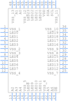
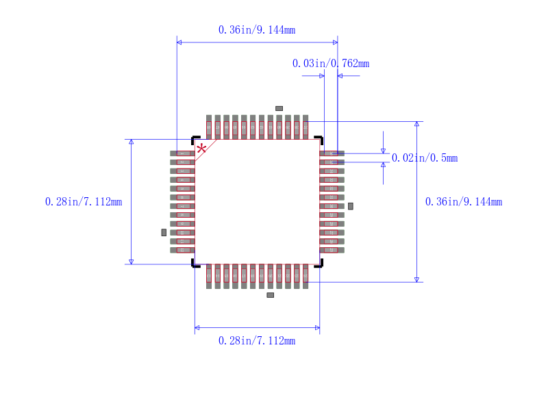
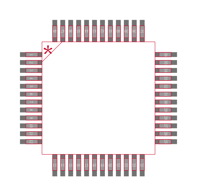
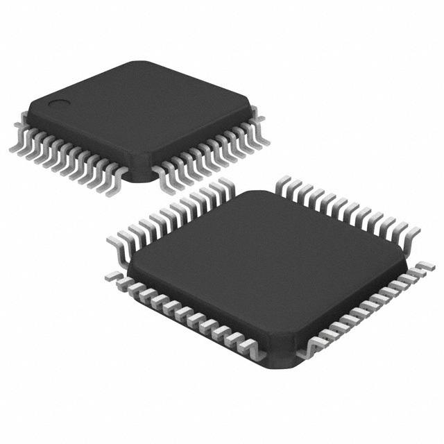
* Packages offered: LQFP48
## Target Applications
* RGB or RGBA LED drivers
* LED status information
* LED displays
* LCD backlights
* Keypad backlights for cellular phones or handheld devices
## Features
频率 100kHz ~ 1MHz
输出接口数 24
输入电压DC 2.30V ~ 5.50V
输出电压 40 V
输出电流 100 mA
供电电流 18000 mA
针脚数 48
耗散功率 1800 W
开关频率 1 MHz
输入电压Max 5.5 V
输入电压Min 2.3 V
输出电流Max 100 mA
工作温度Max 85 ℃
工作温度Min -40 ℃
耗散功率Max 1800 mW
电源电压 2.3V ~ 5.5V
输入电压 2.3V ~ 5.5V
安装方式 Surface Mount
引脚数 48
封装 LQFP-48
封装 LQFP-48
工作温度 -40℃ ~ 85℃ TA
产品生命周期 Active
包装方式 Tape & Reel TR
制造应用 背光
RoHS标准 RoHS Compliant
含铅标准 Lead Free
REACH SVHC版本 2015/12/17
ECCN代码 EAR99