


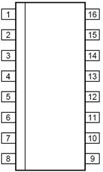
IC I2C 2:1 SELECTOR 16-SOIC
Overview
The PCA9541A is a 2-to-1 I²C-bus master selector designed for high reliability dual master I²C-bus applications where system operation is required, even when one master fails or the controller card is removed for maintenance. The two masters for example, primary and back-up are located on separate I²C-buses that connect to the same downstream I²C-bus slave devices. I²C-bus commands are sent by either I²C-bus master and are used to select one master at a time. Either master at any time can gain control of the slave devices if the other master is disabled or removed from the system. The failed master is isolated from the system and will not affect communication between the on-line master and the slave devices on the downstream I²C-bus.
Two versions are offered for different architectures. PCA9541A/01 with channel 0 selected at start-up, and PCA9541A/03 with no channel selected after start-up.
The interrupt outputs are used to provide an indication of which master has control of the bus. One interrupt input INT_IN collects downstream information and propagates it to the 2 upstream I²C-buses INT0 and INT1 if enabled. INT0 and INT1 are also used to let the previous bus master know that it is not in control of the bus anymore and to indicate the completion of the bus recovery/initialization sequence. Those interrupts can be disabled and will not generate an interrupt if the masking option is set.
A bus recovery/initialization if enabled sends nine clock pulses, a not acknowledge, and a STOP condition in order to set the downstream I²C-bus devices to an initialized state before actually switching the channel to the selected master.
An interrupt is sent to the upstream channel when the recovery/initialization procedure is completed.
An internal bus sensor senses the downstream I²C-bus traffic and generates an interrupt if a channel switch occurs during a non-idle bus condition. This function is enabled when the PCA9541A recovery/initialization is not used. The interrupt signal informs the master that an external I²C-bus recovery/initialization must be performed. It can be disabled and an interrupt will not be generated.
The pass gates of the switches are constructed such that the VDD pin can be used to limit the maximum high voltage, which will be passed by the PCA9541A. This allows the use of different bus voltages on each pair, so that 1.8 V, 2.5 V, or 3.3 V devices can communicate with 5 V devices without any additional protection.
The PCA9541A does not isolate the capacitive loading on either side of the device, so the designer must take into account all trace and device capacitances on both sides of the device, and pull-up resistors must be used on all channels.
External pull-up resistors pull the bus to the desired voltage level for each channel. All I/O pins are 6.0 V tolerant.
An active LOW reset input allows the PCA9541A to be initialized. Pulling the RESET pin LOW resets the I²C-bus state machine and configures the device to its default state as does the internal Power-On Reset POR function.
MoreLess
## Features
* 2-to-1 bidirectional master selector
* I²C-bus interface logic; compatible with SMBus standards
* PCA9541A/01 powers up with Channel 0 selected
* PCA9541A/03 powers up with no channel selected and either master can take control of the bus
* Active LOW interrupt input
* 2 active LOW interrupt outputs
* Active LOW reset input
* 4 address pins allowing up to 16 devices on the I²C-bus
* Channel selection via I²C-bus
* Bus initialization/recovery function
* Bus traffic sensor
* Low Ron switches
* Allows voltage level translation between 1.8 V, 2.5 V, 3.3 V and 5 V buses
* No glitch on power-up
* Supports hot insertion
* Software identical for both masters
* Low standby current
* Operating power supply voltage range of 2.3 V to 5.5 V
* 6.0 V tolerant inputs
* 0 Hz to 400 kHz clock frequency
* ESD protection exceeds 2000 V HBM per JESD22-A114 and 1000 V CDM per JESD22-C101
* Latch-up testing is done to JEDEC Standard JESD78 which exceeds 100 mA
* Packages offered: SO16, TSSOP16, HVQFN16
## Target Applications
* High reliability systems with dual masters
* Gatekeeper multiplexer on long single bus
* Bus initialization/recovery for slave devices without hardware reset
* Allows masters without arbitration logic to share resources
## Features
| 型号/品牌 | 代替类型 | 替代型号对比 |
|---|---|---|
PCA9541AD/03,112 NXP 恩智浦 | 当前型号 | 当前型号 |
PCA9541D/03,112 恩智浦 | 功能相似 | PCA9541AD/03,112和PCA9541D/03,112的区别 |