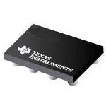
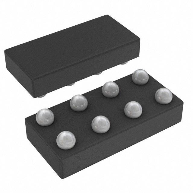
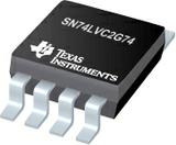
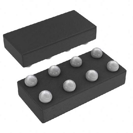
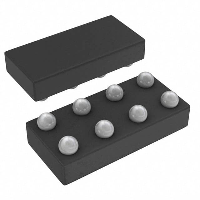
IC 上升沿触发器 SN74LVC2G74YZPR DSBGA marking/标记 CP7
逻辑类型Logic Type| 设置(预设)和复位 SetPreset and Reset \---|--- 电路数Number of Circuits| D型 D-Type 输入数Number of Inputs| 差分 Differential 电源电压VccVoltage - Supply| 1 静态电流IqCurrent - Quiescent Max| 1 输出高,低电平电流Current - Output High, Low| 200MHz 低逻辑电平Logic Level - Low| 4.1ns 高逻辑电平Logic Level - High| 正边沿 Positive Edge 传播延迟时间@Vcc,CLMax Propagation Delay @ V, Max CL| 32mA,32mA Description & Applications| 1.65 V ~ 5.5 V 描述与应用| SINGLE POSIVE-EDGE-TRIGGERED D-TYPE FLIP-FLOP WITH CLEAR AND PRESET DESCRIPTION/ORDERING INFORMATION SN74LVC2G74 SINGLE POSITIVE-EDGE-TRIGGERED D-TYPE FLIP-FLOP WITH CLEAR AND PRESET SCES203M–APRIL 1999–REVISED FEBRUARY 2007 • Available in the Texas Instruments • Typical VOHV Output VOH Undershoot NanoFree™ Package >2 V at VCC = 3.3 V, TA = 25°C • Supports 5-V VCC Operation • I off Supports Partial-Power-Down Mode • Inputs Accept Voltages to 5.5 V Operation • Latch-Up Performance Exceeds 100 mA Per • Max t pd of 5.9 ns at 3.3 V JESD 78, Class II • Low Power Consumption, 10-µA Max ICC • ESD Protection Exceeds JESD 22 • ±24-mA Output Drive at 3.3 V – 2000-V Human-Body Model A114-A • Typical VOLP Output Ground Bounce <0.8 V at V – 200-V Machine Model A115-A CC= 3.3 V, TA= 25°C – 1000-V Charged-Device Model C101 This single positive-edge-triggered D-type flip-flop is designed for 1.65-V to 5.5-V VCC operation. NanoFree™ package technology is a major breakthrough in IC packaging concepts, using the die as the package. A low level at the preset PRE or clear CLR input sets or resets the outputs, regardless of the levels of the other inputs. When PRE and CLR are inactive high, data at the data D input meeting the setup time requirements is transferred to the outputs on the positive-going edge of the clock pulse. Clock triggering occurs at a voltage level and is not related directly to the rise time of the clock pulse. Following the hold-time interval, data at the D input can be changed without affecting the levels at the outputs. This device is fully specified for partial-power-down applications using I off The I off circuitry disables the outputs, preventing damaging current backflow through the device when it is powered down. "Available in the Texas Instruments • Typical VOHV Output VOH Undershoot NanoFree™ Package >2 V at VCC = 3.3 V, TA = 25°C • Supports 5-V VCC Operation • I off Supports Partial-Power-Down Mode • Inputs Accept Voltages to 5.5 V Operation • Latch-Up Performance Exceeds 100 mA Per • Max tpd of 5.9 ns at 3.3 VJESD 78, Class II • Low Power Consumption, 10-µA Max ICC • ESD Protection Exceeds JESD 22 • ±24-mA Output Drive at 3.3 V – 2000-V Human-Body Model A114-A • Typical VOLP Output Ground Bounce <0.8 V at V – 200-V Machine Model A115-A CC= 3.3 V, TA= 25°C 1000-V Charged-Device Model C101"
频率 200 MHz
电源电压DC 5.00 V, 5.50 V max
输出接口数 1
电路数 1
时钟频率 140 MHz
位数 1
传送延迟时间 4.40 ns
极性 Non-Inverting, Inverting
逻辑门个数 2
输入电容 5 pF
输入数 1
工作温度Max 85 ℃
工作温度Min -40 ℃
电源电压 1.65V ~ 5.5V
电源电压Max 5.5 V
电源电压Min 1.65 V
安装方式 Surface Mount
引脚数 8
封装 XFBGA-8
封装 XFBGA-8
工作温度 -40℃ ~ 85℃ TA
产品生命周期 Active
包装方式 Tape & Reel TR
RoHS标准 RoHS Compliant
含铅标准 Lead Free
ECCN代码 EAR99
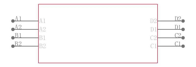
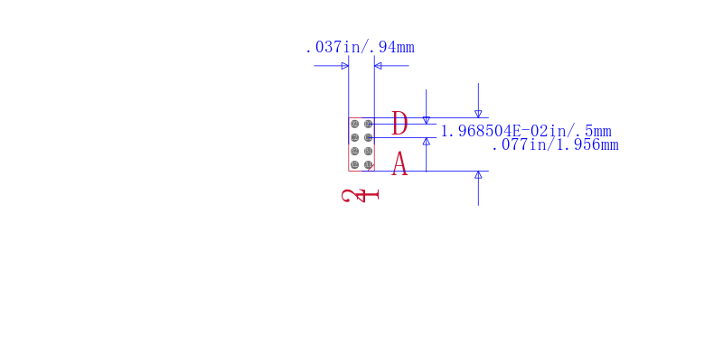

| 型号/品牌 | 代替类型 | 替代型号对比 |
|---|---|---|
SN74LVC2G74YZPR TI 德州仪器 | 当前型号 | 当前型号 |
SN74LVC2G80DCUR 德州仪器 | 类似代替 | SN74LVC2G74YZPR和SN74LVC2G80DCUR的区别 |
SN74LVC2G79DCUR 德州仪器 | 类似代替 | SN74LVC2G74YZPR和SN74LVC2G79DCUR的区别 |
SN74LVC2G79DCTR 德州仪器 | 类似代替 | SN74LVC2G74YZPR和SN74LVC2G79DCTR的区别 |