M68HC12 Microcontrollers
Introduction
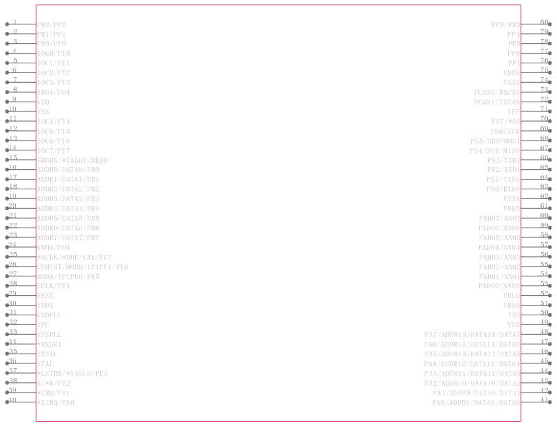
The 68HC912D60 microcontroller unit MCU is a 16-bit device available in two package options, 80-pin QFP and 112-pin TQFP. On chip peripherals include a 16-bit central processing unit CPU12, 60K bytes of flash EEPROM 68HC912D60 or ROM 68HC12D60, 2K bytes of RAM, 1K bytes of EEPROM, two asynchronous serial communication interfaces SCI, a serial peripheral interface SPI, an enhanced capture timer ECT, two one on 80QFP 8-channel,10-bit analog-to-digital converters ATD, a four-channel pulse-width modulator PWM, and a CAN 2.0 A, B software compatible module MSCAN12. System resource mapping, clock generation, interrupt control and bus interfacing are managed by the lite integration module LIM. The 68HC912D60 has full 16-bit data paths throughout, however, the external bus can operate in an 8-bit narrow mode so single 8-bit wide memory can be interfaced for lower cost systems. The inclusion of a PLL circuit allows power consumption and performance to be adjusted to suit operational requirements. In addition to the I/O ports available in each module, 16 2 on 80QFP I/O port pins are available with Key-Wake-Up capability from STOP or WAIT mode.
Features
• 16-bit CPU12
– Upward compatible with M68HC11 instruction set
– Interrupt stacking and programmer’s model identical to M68HC11
– 20-bit ALU
– Instruction queue
– Enhanced indexed addressing
• Multiplexed bus
– Single chip or expanded
– 16 address/16 data wide or 16 address/8 data narrow mode
• Two 8-bit ports with key wake-up interrupt 2 pins only are available on 80QFP and one I2C start bit detector 112TQFP only
• Memory
– 60K byte flash EEPROM, made of a 28K module and a 32K module with 8K bytes protected BOOT section in each module 68HC912D60
– 60K byte ROM 68HC12D60
– 1K byte EEPROM
– 2K byte RAM
• Analog-to-digital converters
– 2 x 8-channels, 10-bit resolution in 112TQFP
– 1 x 8-channels, 8-bit resolution in 80QFP
• 1M bit per second, CAN 2.0 A, B software compatible module
– Two receive and three transmit buffers
– Flexible identifier filter programmable as 2 x 32 bit, 4 x 16 bit or 8 x 8 bit
– Four separate interrupt channels for Rx, Tx, error and wake-up
– Low-pass filter wake-up function
– In 80QFP, only TxCAN and RxCAN pins are available
– Loop-back for self test operation
– Programmable link to a timer input capture channel, for time stamping and network synchronization.
• Enhanced capture timer ECT
– 16-bit main counter with 7-bit prescaler
– 8 programmable input capture or output compare channels; 4 of the 8 input captures with buffer
– Input capture filters and buffers, three successive captures on four channels, or two captures on four channels with a capture/compare selectable on the remaining four
– Four 8-bit or two 16-bit pulse accumulators
– 16-bit modulus down-counter with 4-bit prescaler
– Four user-selectable delay counters for signal filtering
• 4 PWM channels with programmable period and duty cycle
– 8-bit 4-channel or 16-bit 2-channel
– Separate control for each pulse width and duty cycle
– Center- or left-aligned outputs
– Programmable clock select logic with a wide range of frequencies
• Serial interfaces
– Two asynchronous serial communications interfaces SCI
– MI-Bus implemented on final devices
– Synchronous serial peripheral interface SPI
• LIM light integration module
– WCR windowed COP watchdog, real time interrupt, clock monitor
– ROC reset and clocks
– MEBI multiplexed external bus interface
– MBI internal bus interface and map
– INT interrupt control
• Clock generation
– Phase-locked loop clock frequency multiplier
– Limp home mode in absence of external clock
– Slow mode divider
– Low power 0.5 to 16 MHz crystal oscillator reference clock
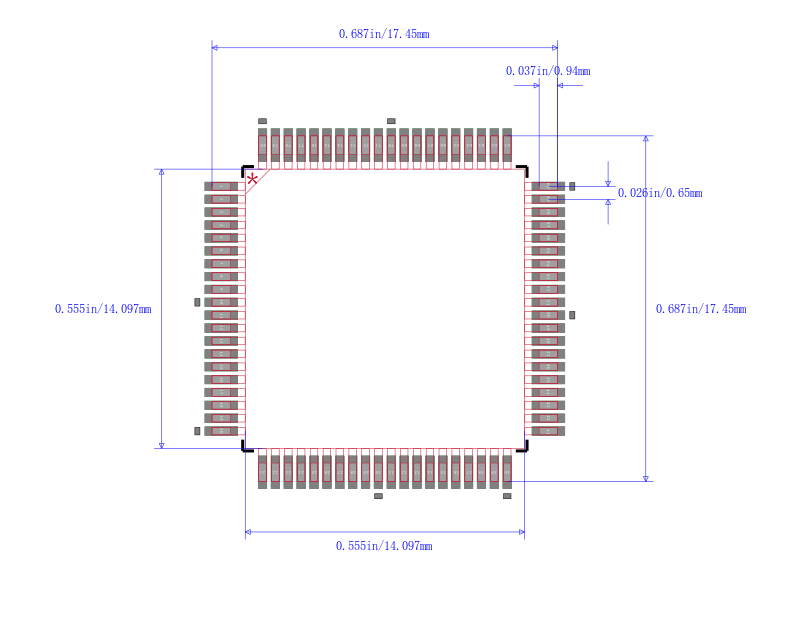
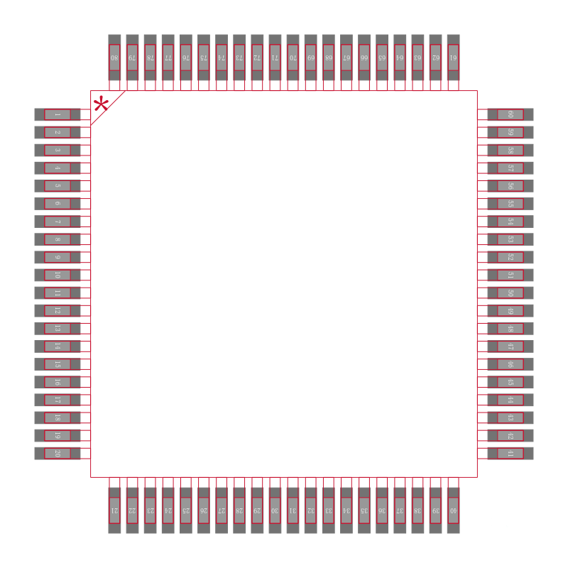
• 112-Pin TQFP package or 80-pin QFP package
– Up to 68 general-purpose I/O lines, plus up to 18 input-only lines in 112TQFP or Up to 48 general-purpose I/O lines, plus up to 10 input-only lines in 80QFP
• 8MHz operation at 5V
• Development support
– Single-wire background debug™ mode BDM
– On-chip hardware breakpoints