stepper-motors [Smoothieware]
主要资料来自官网,这儿直接上图吧
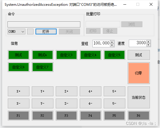
沙冰主板支持G代码,所以核心是如何编写G代码。
发送相关命令:
# 打开mos(我习惯叫他指示灯) M800 M802 M804 M806 M808 M810 #位置移动 X到100 速度3000,Y移动到100 速度3000 Z移动到100 速度3000 G0 X100 F3000 Y100 F3000 Z100 F3000 G0 X10 F3000 Y10 F3000 Z0 F3000 G0 X100 F3000 Y100 F3000 Z100 F3000 G0 X40 F3000 Y10 F3000 Z0 F3000 # 关闭mos M801 M803 M805 M807 M809 M811 # 查询温度 M115 # 其他代码请找官方文档 下面是一些官方的demo
supported-g-codes [Smoothieware]
有时打开很慢, 先记录下来
| G-Code | Description | Example |
|---|---|---|
| G0 | Move to the given coordinates. To the contrary of G1, if there is a tool it will most of the time be off during this kind of move. This is a “go to” move rather than a “do while going to” move. The F parameter defines speed and is remembered by subsequent commands ( specified in millimetres/minute ) (command is modal) | G0 X10 Y5 F100 |
| G1 | Move to the given coordinates, see above for difference with G0. Takes the same F parameter as G0. (command is modal) | G1 X20 Y2.3 F200 |
| G2 | Clockwise circular motion : go to point with coordinates XYZ while rotating around point with relative coordinates IJ (command is not modal) | G2 X10 J5 |
| G3 | Counter-clockwise motion : see above (command is not modal) | G3 Y5 X10 I2 |
| G4 | Dwell S<seconds> or P<milliseconds>, In grbl mode P is float seconds to comply with gcode standards | G4 P1000 |
| G10 | Do firmware extruder retract | G10 |
| G11 | Do firmware extruder un-retract | G11 |
| G10 L1 | Set extruder tool offset for specified extruder where Pn is the extruder number 1 (T0 is P1, T1 is P2), This stays set until reset. Permanent change must be added to config, Only active when multiple extruders have been defined | G10 L1 P2 X10 |
| G10 L2, G10 L20 | Set workspace coordinateshttp://linuxcnc.org/docs/html/gcode/coordinates.htmlandhttp://linuxcnc.org/docs/html/gcode/g-code.html#gcode:g10-l2 | G10 L2 P1 X0 |
| G17 | Select XYZ plane (command is modal) | G17 |
| G18 | Select XZY plane (command is modal) | G18 |
| G19 | Select YZX plane (command is modal) | G19 |
| G20 | Inch mode : passed coordinates will be considered as Inches, so internally translated to millimeters (command is modal) | G20 |
| G21 | Millimeter mode (default) : passed coordinates will be considered as millimeters (command is modal) | G21 |
| G28 | Home The given axis, or if no axis specified home all axis at the same time (edge)in CNC/grbl mode this is move to park position, use$Hto home | G28 |
| G28.1 | Set Predefined Position - This position will be returned to by G28.2 | G28.1 |
| G28.2 | Move to Predefined Position - This perform a rapid move to the Predefined position set by G28.1 (in grbl mode this will do a home) | G28.2 |
| G28.3 | Manual Homing - This allows you to set a home position manually without moving to limit switches | G28.3 |
| G28.4 | Manual Homing based on actuator position- This allows you to set a home position manually based on actuator position (used for rotary delta) | G28.4 |
| G28.5 | Clears the homed flag for the specified axis, or all if not specifed | G28.5G28.5 Z0 |
| G28.6 | Shows the homing status of each axis | G28.6 |
| G29 | Probes the bed and outputs the bed heights depending on levelling strategy selected, seeZProbe | G29 |
| G30 | Simple Z probe at current XY, reports distance moved down until probe triggers. optional F parameter defines the speed of probing, zprobe.slow_feedrate is used when not supplied | G30 G30 F100 |
| G31 | Depends on levelling strategy selected, see ZProbe | G31 |
| G32 | Depends on levelling strategy selected, see ZProbe. For calibration on delta, uses Z probe to calibrate delta endstops and arm radius, use R parameter to select only arm radius calibration and E to select only endstop calibration. I to set target precision, J to set probe_radius, K to keep current endstop trim settings. In Zgrid module, it starts the grid probing | G32 G32 R G32 E G32 EK G32 I0.02 |
| G38.2 G38.3 G38.4 G38.5 | Standard probe commands implemented as documented here | G38.2 Z-10 |
| G43.2 | Baby steps | G43.2 Z0.05 |
| G53 | Must be on a line by itself OR the first G code on a line, the directly following G0/G1 will be executed in MCS coordinates | G53 G0 X0 Y0 |
| G54-G59.3 | use workspace coordinates http://linuxcnc.org/docs/html/gcode/coordinates.html and http://linuxcnc.org/docs/html/gcode/g-code.html#gcode:g54-g59.3 | G54 |
| G90 | Absolute mode ( default ) (command is modal) | G90 |
| G91 | Relative mode (command is modal) | G91 |
| G92 | Set global workspace coordinate system to specified coordinates http://linuxcnc.org/docs/html/gcode/g-code.html#gcode:g92 | G92 X0 Y0 Z0 |
| G92.1 | Clear the G92 and G30 Znnn offsets | G92.1 |
| G92.4 | manually set homing (MCS) for XYZ | G92.4 X0 Y0 Z0 |
| M-Code | Description | |
| M3 | Starts the spindle. Only if spindle module is enabled. The S parameter sets the speed in rotations per minute | M3 S5000 |
| M5 | Stops the spindle Only if spindle module is enabled. | M5 |
| M7 | Starts the mist switch for CNC (Need to create a switch called : switch.mist.enable). | M7 |
| M8 | Starts the flood switch for CNC (Need to create a switch called : switch.flood.enable). | M8 |
| M9 | Stops the mist and flood at same time (like LinuxCNC and GRBL). | M9 |
| M17 | Enable stepper motors | M17 |
| M18 | Disable stepper motors. With a parameter it will disable that stepper motor A will disable extruder 1 B will disable extruder 2. E0 will disable the currently selected extruder | M18 M18 X0 M18 E0 |
| M20 | List SD card files | M20 |
| M21 | Initialize the SD card. This does nothing in Smoothie but is kept for compatibility | M21 |
| M23 | Select a file filename be lowercase | M23 file.gcode |
| M24 | Start or resume SD card print | M24 |
| M25 | Pause SD card print | M25 |
| M26 | Abort a SD card print | M26 |
| M27 | Report print progress | M27 |
| M28 | Begin write to SD card. Use M29 to indicate end of file. | M28 file.gcode |
| M29 | End write to SD card. Used to end file write started with M28. | M29 |
| M30 | Delete a file on the SD card | M30 file.gcode |
| M32 | Select a file, and start playing it | M32 file.gcode |
| M82 | Set absolute mode for extruder only | M82 |
| M83 | Set relative mode for extruder only | M83 |
| M84 | Disable steppers | M84 |
| M92 | Set axis steps per mm for XYZ axis and/or ABC axis (M92 A100 sets A axis if it is NOT an extruder) | M92 X200 M92 A1000 |
| M104 | Set Extruder Temperature - S<temperature> | M104 S190 |
| M105 | Read current temp | M105 |
| M106 | Turn fan ON | M106 |
| M107 | Turn fan OFF | M107 |
| M109 | Set Extruder Temperature and Wait - S<temperature> | M109 S190 |
| M110 | Set current line number -N<line number> | N123 M110 |
| M112 | Halt all operations, turn off heaters, go into Halt state | M112 |
| M114 | Show current position of all axes, XYZ will be the last requested position | M114 |
| M114.1 | Show current real time position of all axes | M114.1 |
| M114.2 | Show current real time machine position of all axes | M114.2 |
| M114.3 | Show current real time actuator position of all actuators | M114.3 |
| M114.4 | Show last milestone | M114.4 |
| M114.5 | Show last machine position | M114.5 |
| M117 | Display message on LCD, blank message will clear it | M117 hello world M117 |
| M119 | Show limit switch status | M119 |
| M120 | “Push” the current feed-rate and seek-rate so that another one can be temporarily used, then the current one can be restored | M120 |
| M121 | “Pop” the current feed-rate and seek-rate, see M120 | M121 |
| M140 | Set Bed Temperature - S<temperature> | M140 S55 |
| M143 | Set Maximum Temperature - S<heater index> P<temperature> | M143 S0 P300 |
| M190 | Set Bed Temperature and Wait - S<temperature> | M190 S55 |
| M200 | Set E units for volumetric extrusion - D<filament diameter> set to 0 to disable volumetric extrusion | M200 D3.0 |
| M203 | Set maximum cartesian feedrate your machine can sustain <mm/sec> | M203 X100 Y100 Z100 E10 |
| M203.1 | Set maximum actuator feedrate your machine can sustain <mm/sec> | M203.1 X100 Y100 Z100 |
| M203 Vnnn | Set maximum volumetric rate your extruider/hotend can sustain where nnn is <mm³/sec> | M203 V50 |
| M204 | S<acceleration> Set default acceleration in mm/sec² NB setting axis acceleration will mean that the acceleration for a given move will be the lowest of the axis specified, the default is used if a specific axis is not set | M204 S1000 X500 Z100 E500 |
| M205 | X<junction deviation> Z<z junction deviation> S<minimum planner speed>, Z junction deviation only applies to z only moves, 0 disables junction deviation for Z, -1 uses global junction deviation | M205 X0.05 S30.0 |
| M206 | Set homing offsets | M206 X10 Y3 Z0.5 |
| M207 | Set retract length Smm Fmm/min Zzlift/hop Qfeedrate mm/min | M207 S4 F30 Z1 |
| M208 | Set retract recover length Smm surplus to the M207 S* Fmm/min | M208 S0 F8 |
| M220 | S<factor in percent>- set speed factor override percentage | M220 S50 |
| M221 | S<flow rate factor in percent>- set flow rate factor override percentage for current extruder | M221 S50 |
| M301 | Edit temperature control PID parameters X<i_max> Y<max_pwm> | M301 S0 P30 I10 D10 X255.0000 Y255 |
| M303 | Begin PID auto-tune cycle E<hotendid> S<temperature> | M303 E0 S185 - Tune extruder - M303 E1 S100 - Tune printbed - |
| M304 | Abort PID auto-tuning | M304 |
| M305 | Set parameters for the thermistor, where B is beta, R is r0 and X is t0; P is the ID from the thermistors list (use console command Thermistors to get a list). | M305 B4066 |
| M306 | Set homing offsets based on current position, subtracts current position from homing offset for specified axis | M306 Z0 |
| M360 | Scara Morgan: Move to Theta 0 degree position. Adding P0 will save the current arm position as the Theta 0 degree position | M360 M360 P0 |
| M361 | Scara Morgan: Move to Theta 90 degree position. Adding P0 will save the current arm position as the Theta 90 degree position | M361 M361 P0 |
| M364 | Scara Morgan: M364: Move to Psi + Theta 90 degree position. Adding P0 will save the current arm position as the Psi + Theta 90 degree position | M364 M364 P0 |
| M370 | Z grid strategy: clears the ZGrid and the bed levelling is disabled until G32 is run again. | M370 |
| M374 | Z grid strategy: save calibration grid. | M374 |
| M375 | Z grid strategy: load calibration grid. | M375 |
| M375.1 | display the current grid | M375.1 |
| M400 | Wait for the queue to be empty and the motors to stop before the M400 answers ok | M400 |
| M407 | Get filament detector information | M407 |
| M500 | Save some volatile settings to an override file | M500 |
| M501 | Load config-override file optionally specifying the extension | M501 - loads config-override, M501 test1 - loads config-override.test1 |
| M502 | Delete the override file, reverting to config settings at next reset | M502 |
| M503 | Display overridden settings if any | M503 |
| M504 | Save the settings to an override file with specified extension | M504 test1 - saves to config-override.test1 |
| M557 | Defines probe points | M557 P1 X30 Y40.5 |
| M561 | Clears the plane and the bed leveling is disabled until G32 is run again | M561 |
| M565 | Defines the probe offsets from the nozzle or tool head | M565 X3 Y4.5 Z-2.37 |
| M600 | Suspend print in progress (use M601 to continue) | M600 |
| M601 | Resume suspended print | M601 |
| M665 | Set arm solution specific settings: Delta - L<arm length> R<arm radius> Z<max height> | M665 L341.0 R350 Z430 |
| M666 | On a delta sets trim values for the endstops. (Positive values will crash physical endstops.) | M666 X-0.1 Y-0.2 Z-0.3 |
| M670 | ZProbe feedrates Slow/fast(K)/Return (mm/sec) max_z (mm) height (mm) | M670 S5.00 K100.00 R0.00 Z357.55 H5.00 |
| M906 | Set Current in milliamp for SPI drivers, only if the driver is handled by the motorcontrol module | M906 A1000 B1100 |
| M907 | Set Current control via digipot for each axis (current in amps) | M907 X1.0 Y1.0 Z1.0 A1.5 |
| M909 | Set microsteps (1/n), ONLY for advanced drivers handled by motordriver module, M909.1 will also set the steps/mm accordingly | M909 A16 B64 |
| M910.x | Setup advanced driver chips that support SPI setup, parameters are specific to each chip see chip docs | M910 |
| M957 | (with Spindle module enabled) Report the current spindle speed and PWM value | M957 |
| M958 | (with Spindle module enabled) Report the current spindle PID parameters. M958 Px.xx Ix.xx Dx.xx will set them (to save the new values, you need to edit config file manually). | M958 P0.1 |
| M999 | Reset from a halted state caused by limit switch, M112 or kill switch | M999 |
G Code comments begin at a semicolon, and end at the end of the line: Example:
G0 X7 Y8 ;this is the comment
ADDITIONAL CODES
The Smoothieware configuration file permits the association of additional codes with some tool functions. For example, for a Switch module, you can specify an arbitrary command in the 'input_on_command' and 'input_off_command'. This means that some additional codes may be available, depending on your specific configuration file.
For example, if you are using servos, then you will likely have configured the following commands:
| G-Code | Description | Example | |
|---|---|---|---|
| M280 | Move servo to S<position> where position is 0-100 | M280 S20 ; move servo to position 20 = 20% duty cycle | |
| M281 | Turn off servo | M281 ; Same as M280 S0 0% duty cycle, effectively off |
Additionally, in your configuration, you can assign sub-commands to deal with multiple tools of the same type, for example:
| G-Code | Description | |
|---|---|---|
| M280.1 | Move your first servo | |
| M280.2 | Move your second servo |
TOOL CHANGE
Tn will change the tool to n for all future commands, it may appear anywhere on the line or on a line by itself T1 M200 M200 T1
This is not compatible with the G-code spec, but unfortunately most slicers create incorrect Gcode for tool change.
Note in smoothie there must be a space in front of a line that is affected by a modal G code. Some G code processors like HeeksCNC don't prefix the space neither do they prefix each line with the modal G code.