??Arduino它是一个广泛使用的电子原型平台,包括硬件(各种型号的开发板)和软件(Arduino IDE),Arduino通过传感器的数据感知,实现环境感知功能依赖于各种传感器(温湿度传感器、空气质量传感器等),Arduino环境可照明、转子等装置反馈或改变环境。
??Modbus是工业电子设备间通信的行业标准,可通过串口、以太网等支持互联网协议的网络进行通信。
??ModbusTCP使用以太网TCP/IP实现的Modbus我们可以使用带网络扩展板的通信协议Arduino制作开发板Modbus从机。通过Modbus我们向协议的通信指令向Arduino通过改变寄存器寄存器的状态,发送指令来控制照明。
??接下来我们开始组装Arduino,使用的零件如下:
| 序 | 零件名称 | 数量 |
|---|---|---|
| 1 | Arduino UNO R3 开发板 | 1 |
| 2 | Arduino Ethernet W5100 网络扩展板 | 1 |
| 3 | USB数据线 | 1 |
| 4 | 网线 | 1 |
| 5 | 面包板 | 1 |
| 6 | 杜邦线 | 若干 |
| 7 | LED灯 | 1 |
| 8 | 220欧姆电阻 | 1 |
??Arduino开发板与Ethernet W5100网络扩展板组装后的外观如下图所示。 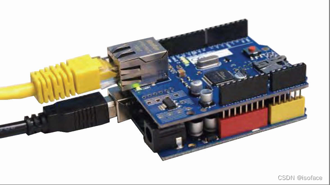 ??我们设计的程序的流程如下: ??使用Arduino IDE 编译并上传以下内容Arduino程序。
// 采用 MyArduinoProjects Modbus TCP 链接库 // http://myarduinoprojects.com/modbus.html #include <SPI.h> #include <Ethernet.h>  #include "MgsModbus.h" //引入Modbus TCP 链接库 MgsModbus Mb;  // 设置网络 (网络扩展卡 MAC 可自行修改 1 避免冲突) byte mac[] = {
       0x90, 0xA2, 0xDA, 0x0E, 0x94, 0xB6 };     //设置Arduino设备的网卡MAC地址 IPAddress ip(192, 168, 1, 162);     //设置Arduino设备的网络IP地址 IPAddress gateway(192, 168, 1, 1);  //设置网关IP地址 IPAddress subnet(255, 255, 255, 0); //设置子网掩码

#define LED_PIN 8 //定义LED PIN为8
int LedSwitch=0;

void setup() {

   Serial.begin(9600);
   Ethernet.begin(mac, ip, gateway, subnet);         // 启动网络
   Serial.println("网络已经开通");

   //设置要使用的缓存器地址
   //0 1 2 3 4 是 Holding 缓存器的顺序,其地址分别是10000,10001,10002,10003,10004
   // 新增缓存器 mb.MbData(i);
   Mb.MbData[0] = 0;                                 // 0=关闭LED灯 1=打开LED灯
   pinMode(LED_PIN, OUTPUT);                         // 设定脚位 PIN 8为输出模式
}

void loop() {

   LedSwitch=Mb.MbData[0];                           // 读取数字缓存器的数值
   if (LedSwitch!=0){

       digitalWrite(LED_PIN, HIGH);                  //PIN 8输出为HIGH,LED点亮
   }
   else {

   digitalWrite(LED_PIN, LOW);                       //PIN 8输出为LOW,LED熄灭
   }
   delay(500);                                       //延时 0.5秒
   Mb.MbsRun();                                      //呼叫 Modbus
}
上述设计完成后,我们使用FastWeb网页开发平台快速设计界面。
点击右侧的开关图像,开关打开,上方的灯泡切换为亮灯的状态,同时连接Arduino开发板的LED发光二极管处于点亮的状态;在亮灯状态下,点击右侧的开关图像,开关关闭,上方的灯泡切换为灯灭的状态,同时连接Arduino开发板的LED发光二极管处于关闭的状态。
- :https://www.isoface.cn/isoface/production/software/fastweb/web
- :https://www.isoface.cn/isoface/component/k2/video-tutorial/fastweb/w-eq-dem-2001
- :https://www.isoface.cn/isoface/doc/fastweb/demo/modbustcp-led/
- :https://www.isoface.cn
- :309174897