本文以5为基础.0-1.0-PUB — PCI Express? Base Specification Revision 5.0 Version 1.翻译和理解0
PCIe 5.1 - Introduction
- 1 Introduction
-
- 1.1 A Third Generation I/O Interconnect
- 1.2 PCI Express Link
- 1.3 PCI Express Fabric Topology
-
- 1.3.1 Root Complex
- 1.3.2 Endpoints
-
- 1.3.2.1 Legacy Endpoint Rules
- 1.3.2.2 PCI Express Endpoint Rules
- 1.3.2.3 Root Complex Integrated Endpoint Rules
- 1.3.3 Switch
- 1.3.4 Root Complex Event Collector
- 1.3.5 PCI Express to PCI/PCI-X Bridge
- 1.4 Hardware/Software Model for Discovery, Configuration and Operation
- 1.5 PCI Express Layering Overview
-
- 1.5.1 Transaction Layer
- 1.5.2 Data Link Layer
- 1.5.3 Physical Layer
- 1.5.4 Layer Functions and Services
-
- 1.5.4.1 Transaction Layer Services
- 1.5.4.2 Data Link Layer Services
- 1.5.4.3 Physical Layer Services
- 1.5.4.4 Inter-Layer Interfaces
-
- 1.5.4.4.1 Transaction/Data Link Interface
- 1.5.4.4.2 Data Link/Physical Interface
1 Introduction
This chapter presents an overview of the PCI Express architecture and key concepts. PCI Express is a high performance, general purpose I/O interconnect defined for a wide variety of future computing and communication platforms. Key PCI attributes, such as its usage model, load-store architecture, and software interfaces, are maintained, whereas its parallel bus implementation is replaced by a highly scalable, fully serial interface. PCI Express takes advantage of recent advances in point-to-point interconnects, Switch-based technology, and packetized protocol to deliver new levels of performance and features. Power Management, Quality of Service (QoS), Hot-Plug/hot-swap support, data integrity, and error handling are among some of the advanced features supported by PCI Express. 本章概述了PCIExpress结构和关键概念。PCIExpress是一种高性能、通用的I/O互联可用于未来的各种计算和通信平台。保持关键PCI属性,如其使用模型、负载存储架构和软件接口,并行总线被高度可伸缩和完全串行的接口所取代。PCIe利用点对点互连、基于交换的技术和分组协议的最新进展,提供更新级别的性能和特点。电源管理,服务质量(QoS)、热插头/热插拔支持、数据完整性和错误处理PCIe支持的一些高级功能之一。
1.1 A Third Generation I/O Interconnect
The high-level requirements for this third generation I/O interconnect are as follows: 该第三代I/O互联的高级要求如下:
- Supports multiple market segments and emerging applications:
- 支持多个细分市场和新兴应用。
- Unifying I/O architecture for desktop, mobile, workstation, server, communications platforms, and embedded devices
- 统一桌面、移动、工作站、服务器、通信平台和嵌入式设备I/O架构
- Ability to deliver low cost, high volume solutions:
- 能够提供低成本、高质量的解决方案。
- Cost at or below PCI cost structure at the system level
- 成本处于或低于系统水平PCI成本结构
- Support multiple platform interconnect usages:
- 支持各种平台的互联使用。
- Chip-to-chip, board-to-board via connector or cabling
- 芯片对芯片和板对板的连接通过连接器或电缆实现
- A variety of mechanical form factors:
- 各种机械形式的因素。
- [M.2], [CEM] (Card Electro-Mechanical), [U.2], [OCuLink]
- PCI-compatible software model:
- 与PCI兼容软件模型
- Ability to enumerate and configure PCI Express hardware using PCI system configuration software implementations with no modifications
- 能够使用PCI实现正确的系统配置软件PCIe无需修改硬件的枚举和配置
- Ability to boot existing operating systems with no modifications
- 能够在不修改的情况下启动现有的操作系统
- Ability to support existing I/O device drivers with no modifications
- 支持现有的I/O无需修改设备驱动程序 li>Ability to configure/enable new PCI Express functionality by adopting the PCI configuration paradigm
- 通过采用PCI配置范式,能够配置/启用新的PCIe功能
- Performance:
- 性能
- Low-overhead, low-latency communications to maximize application payload bandwidth and Link efficiency
- 低开销、低延迟的通信,使应用有效载荷带宽和链接效率最大化
- High-bandwidth per pin to minimize pin count per device and connector interface
- 每个引脚的高带宽,以尽量减少每个设备和连接器接口的引脚数
- Scalable performance via aggregated Lanes and signaling frequency
- 通过聚合lanes和信令频率实现可扩展的性能
- Advanced features:
- 高级功能
- Comprehend different data types and ordering rules
- 理解不同的数据类型和排序规则
- Power management and budgeting
- 电源管理和编制
- Ability to identify power management capabilities of a given Function
- 能够识别特定功能的电源管理能力
- Ability to transition a Function into a specific power state
- 能够将一个功能过渡到一个特定的电源状态
- Ability to receive notification of the current power state of a Function
- 能够接收一个功能的当前电源状态的通知
- Ability to generate a request to wakeup from a power-off state of the main power supply
- 能够产生从主电源 power-off状态下唤醒的请求
- Ability to sequence device power-up to allow graceful platform policy in power budgeting
- 能够对设备上电进行排序,以便在电源预算中实现宽松的平台策略
- Ability to support differentiated services, i.e., different (QoS)
- 支持差异化服务的能力,即不同的(QoS)
- Ability to have dedicated Link resources per QoS data flow to improve fabric efficiency and effective application-level performance in the face of head-of-line blocking
- 能够为每个 QoS 数据流提供专用链路资源,以在面对线头阻塞时提高结构效率和有效的应用程序级性能
- Ability to configure fabric QoS arbitration policies within every component
- 能够在每个组件中配置结构 QoS 仲裁策略
- Ability to tag end-to-end QoS with each packet
- 能够用每个数据包标记端到端的QoS
- Ability to create end-to-end isochronous (time-based, injection rate control) solutions
- 有能力创建端到端的等时性(基于时间、注入率控制)解决方案
- Hot-Plug support
- 热插拔功能的支持
- Ability to support existing PCI Hot-Plug solutions
- 有能力支持现有的PCI热插拔解决方案
- Ability to support native Hot-Plug solutions (no sideband signals required)
- 能够支持本地热插拔解决方案(不需要边带信号)
- Ability to support async removal
- 能够支持异步移除
- Ability to support a unified software model for all form factors
- 有能力支持所有形式因素的统一软件模型
- Data Integrity
- 数据的完整性
- Ability to support Link-level data integrity for all types of transaction and Data Link packets
- 能够为所有类型的事务和数据链路包文支持链路级数据完整性
- Ability to support end-to-end data integrity for high availability solutions
- 有能力支持高可用性解决方案的端到端数据完整性
- Error handling
- 错误处理
- Ability to support PCI-level error handling
- 能够支持PCI级别的错误处理
- Ability to support advanced error reporting and handling to improve fault isolation and recovery solutions
- 有能力支持先进的错误报告和处理,以改进故障隔离和恢复方案
- Process Technology Independence
- 工艺技术的独立性
- Ability to support different DC common mode voltages at Transmitter and Receiver
- 能够支持发射器和接收器的不同直流共模电压
- Ease of Testing
- 测试的便捷性
- Ability to test electrical compliance via simple connection to test equipment
- 能够通过与测试设备的简单连接来测试电气符合性
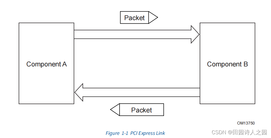
1.2 PCI Express Link
A Link represents a dual-simplex communications channel between two components. The
fundamental PCI Express Link consists of two, low-voltage, differentially driven signal pairs:
a Transmit pair and a Receive pair as shown in Figure 1-1.
链接代表了两个组件之间的双复式通信通道。基本的PCIe Link由两个低电压、差分驱动的信号对组成:如图1-1所示,一个发送对和一个接收对。
 The primary Link attributes for PCI Express Link are: PCIe Link的主要链接属性是:
- The basic Link - PCI Express Link consists of dual unidirectional differential Links, implemented as a Transmit pair and a Receive pair. A data clock is embedded using an encoding scheme to achieve very high data rates.
- 基本链路–PCIe链路由两个单向差分链路组成,实现为一对发送和一对接收。使用编码方案嵌入时钟数据,以实现非常高的数据速率。
- Signaling rate - Once initialized, each Link must only operate at one of the supported signaling levels.
- 信令速率 - 一旦初始化,每个链路必须只在支持的信令水平中的一个运行。
- For the first generation of PCI Express technology, there is only one signaling rate defined, which provides an effective 2.5 Gigabits/second/Lane/direction of raw bandwidth.
- 对于第一代PCI Express技术,只定义了一个信令速率,它提供了有效的2.5 Gigabits/second/Lane/direction原始带宽。
- The second generation provides an effective 5.0 Gigabits/second/Lane/direction of raw bandwidth.
- 第二代产品提供有效的5.0 Gigabits/second/Lane/direction的原始带宽。
- The third generation provides an effective 8.0 Gigabits/second/Lane/direction of raw bandwidth.
- 第三代产品提供有效的8.0 Gigabits/second/Lane/direction的原始带宽。
- The fourth generation provides an effective 16.0 Gigabits/second/Lane/direction of raw bandwidth.
- 第四代产品提供了有效的16.0 Gigabits/second/Lane/direction的原始带宽。
- The fifth generation provides an effective 32.0 Gigabits/second/Lane/direction of raw bandwidth.
- 第五代产品提供了有效的32.0 Gigabits/second/Lane/direction的原始带宽。
- Lanes - A Link must support at least one Lane - each Lane represents a set of differential signal pairs (one pair for transmission, one pair for reception). To scale bandwidth, a Link may aggregate multiple Lanes denoted by xN where N may be any of the supported Link widths. A x8 Link operating at the 2.5 GT/s data rate represents an aggregate bandwidth of 20 Gigabits/second of raw bandwidth in each direction. This specification describes operations for x1, x2, x4, x8, x12, x16, and x32 Lane widths.
- lanes - 一个链路必须支持至少一个lane - 每个lane代表一组差分信号对(一对用于传输,一对用于接收)。为了扩大带宽,一个链路可以聚集多个lanes,用xN表示,其中N可以是任何支持的链路宽度。在2.5GT/s数据速率下运行的x8链路代表了每个方向20 Gigabits/second的原始带宽的聚合带宽。本规范描述了x1、x2、x4、x8、x12、x16和x32通道宽度的操作。
- Initialization - During hardware initialization, each PCI Express Link is set up following a negotiation of Lane widths and frequency of operation by the two agents at each end of the Link. No firmware or operating system software is involved.
- 初始化 - 在硬件初始化过程中,每个PCIe链路都是在链路两端的两个agents 协商lane带宽和操作频率后设置的。不涉及固件或操作系统软件。
- Symmetry - Each Link must support a symmetric number of Lanes in each direction, i.e., a x16 Link indicates there are 16 differential signal pairs in each direction.
- 对称性 - 每个链路必须支持每个方向上的对称数量的Lane,即一个x16链路表示每个方向上有16个差分信号对。
1.3 PCI Express Fabric Topology
A fabric is composed of point-to-point Links that interconnect a set of components - an example
fabric topology is shown in Figure 1-2 . This figure illustrates a single fabric instance
referred to as a Hierarchy - composed of a Root Complex (RC), multiple Endpoints (I/O devices),
a Switch, and a PCI Express to PCI/PCI-X Bridge, all interconnected via PCI Express Links.
一个结构是由点对点的链接组成的,这些链接将一组组件互连 - 图1-2是一个结构拓扑的例子。该图说明了一个被称为层次结构的单一结构实例–由一个根复合体(RC)、多个端点(I/O设备)、一个Switch和一个PCIe到PCI/PCI-X桥组成,所有这些都通过PCIe链路互连。
1.3.1 Root Complex
- An RC denotes the root of an I/O hierarchy that connects the CPU/memory subsystem to the I/O.
- As illustrated in Figure 1-2 , an RC may support one or more PCI Express Ports. Each interface defines a separate hierarchy domain. Each hierarchy domain may be composed of a single Endpoint or a sub-hierarchy containing one or more Switch components and Endpoints.
- The capability to route peer-to-peer transactions between hierarchy domains through an RC is optional and implementation dependent. For example, an implementation may incorporate a real or virtual Switch internally within the Root Complex to enable full peer-to-peer support in a software transparent way. Unlike the rules for a Switch, an RC is generally permitted to split a packet into smaller packets when routing transactions peer-to-peer between hierarchy domains (except as noted below), e.g., split a single packet with a 256-byte payload into two packets of 128 bytes payload each. The resulting packets are subject to the normal packet formation rules contained in this specification (e.g., Max_Payload_Size, Read Completion Boundary (RCB), etc.). Component designers should note that splitting a packet into smaller packets may have negative performance consequences, especially for a transaction addressing a device behind a PCI Express to PCI/PCI-X bridge. Exception: An RC that supports peer-to-peer routing of Vendor_Defined Messages is not permitted to split a Vendor_Defined Message packet into smaller packets except at 128-byte boundaries (i.e., all resulting packets except the last must be an integral multiple of 128 bytes in length) in order to retain the ability to forward the Message across a PCI Express to PCI/PCI-X Bridge.
- An RC must support generation of configuration requests as a Requester.
- An RC is permitted to support the generation of I/O Requests as a Requester. An RC is permitted to generate I/O Requests to either or both of locations 80h and 84h to a selected Root Port, without regard to that Root Port’s PCI Bridge I/O decode configuration; it is recommended that this mechanism only be enabled when specifically needed.
- An RC must not support Lock semantics as a Completer.
- An RC is permitted to support generation of Locked Requests as a Requester.
1.3.2 Endpoints
Endpoint refers to a type of Function that can be the Requester or Completer of a PCI Express transaction either on its own behalf or on behalf of a distinct non-PCI Express device (other than a PCI device or host CPU), e.g., a PCI Express attached graphics controller or a PCI Express-USB host controller. Endpoints are classified as either legacy, PCI Express, or Root Complex Integrated Endpoints (RCiEPs).
1.3.2.1 Legacy Endpoint Rules
- A Legacy Endpoint must be a Function with a Type 00h Configuration Space header.
- A Legacy Endpoint must support Configuration Requests as a Completer.
- A Legacy Endpoint may support I/O Requests as a Completer.
- A Legacy Endpoint is permitted to accept I/O Requests to either or both of locations 80h and 84h, without regard to that Endpoint’s I/O decode configuration.
- A Legacy Endpoint may generate I/O Requests.
- A Legacy Endpoint may support Lock memory semantics as a Completer if that is required by the device’s legacy software support requirements.
- A Legacy Endpoint must not issue a Locked Request.
- A Legacy Endpoint may implement Extended Configuration Space Capabilities, but such Capabilities may be ignored by software.
- A Legacy Endpoint operating as the Requester of a Memory Transaction is not required to be capable of generating addresses 4 GB or greater.
- A Legacy Endpoint is required to support MSI or MSI-X or both if an interrupt resource is requested. If MSI is implemented, a Legacy Endpoint is permitted to support either the 32-bit or 64-bit Message Address version of the MSI Capability structure.
- A Legacy Endpoint is permitted to support 32-bit addressing for Base Address Registers that request memory resources.
- A Legacy Endpoint must appear within one of the hierarchy domains originated by the Root Complex.
1.3.2.2 PCI Express Endpoint Rules
- A PCI Express Endpoint must be a Function with a Type 00h Configuration Space header.
- A PCI Express Endpoint must support Configuration Requests as a Completer.
- A PCI Express Endpoint must not depend on operating system allocation of I/O resources claimed through BAR(s).
- A PCI Express Endpoint must not generate I/O Requests.
- A PCI Express Endpoint must not support Locked Requests as a Completer or generate them as a Requester. PCI Express-compliant software drivers and applications must be written to prevent the use of lock semantics when accessing a PCI Express Endpoint.
- A PCI Express Endpoint operating as the Requester of a Memory Transaction is required to be capable of generating addresses greater than 4 GB.
- A PCI Express Endpoint is required to support MSI or MSI-X or both if an interrupt resource is requested., If MSI is implemented, a PCI Express Endpoint must support the 64-bit Message Address version of the MSI Capability structure.
- A PCI Express Endpoint requesting memory resources through a BAR must set the BAR’s Prefetchable bit unless the range contains locations with read side-effects or locations in which the Function does not tolerate write merging. See Section 7.5.1.2.1 for additional guidance on having the Prefetchable bit Set.
- For a PCI Express Endpoint, 64-bit addressing must be supported for all BARs that have the Prefetchable bit Set. 32-bit addressing is permitted for all BARs that do not have the Prefetchable bit Set.
- The minimum memory address range requested by a BAR is 128 bytes.
- A PCI Express Endpoint must appear within one of the hierarchy domains originated by the Root Complex.
1.3.2.3 Root Complex Integrated Endpoint Rules
- A Root Complex Integrated Endpoint (RCiEP) is implemented on internal logic of Root Complexes that contains the Root Ports.
- An RCiEP must be a Function with a Type 00h Configuration Space header.
- An RCiEP must support Configuration Requests as a Completer.
- An RCiEP must not require I/O resources claimed through BAR(s).
- An RCiEP must not generate I/O Requests.
- An RCiEP must not support Locked Requests as a Completer or generate them as a Requester. PCI Express-compliant software drivers and applications must be written to prevent the use of lock semantics when accessing an RCiEP.
- An RCiEP operating as the Requester of a Memory Transaction is required to be capable of generating addresses equal to or greater than the Host is capable of handling as a Completer.
- An RCiEP is required to support MSI or MSI-X or both if an interrupt resource is requested. If MSI is implemented, an RCiEP is permitted to support either the 32-bit or 64-bit Message Address version of the MSI Capability structure.
- An RCiEP is permitted to support 32-bit addressing for Base Address Registers that request memory resources.
- An RCiEP must not implement Link Capabilities, Link Status, Link Control, Link Capabilities 2, Link Status 2, and Link Control 2 registers in the PCI Express Extended Capability.
- If an RCiEP is associated with an optional Root Complex Event Collector it must signal PME and error conditions through the Root Complex Event Collector.
- An RCiEP must not be associated with more than one Root Complex Event Collector.
- An RCiEP does not implement Active State Power Management.
- An RCiEP may not be hot-plugged independent of the Root Complex as a whole.
- An RCiEP must not appear in any of the hierarchy domains exposed by the Root Complex.
- An RCiEP must not appear in Switches.
1.3.3 Switch
A Switch is defined as a logical assembly of multiple virtual PCI-to-PCI Bridge devices as illustrated in Figure 1-3 . All Switches are governed by the following base rules.
- Switches appear to configuration software as two or more logical PCI-to-PCI Bridges.
- A Switch forwards transactions using PCI Bridge mechanisms; e.g., address-based routing except when engaged in a Multicast, as defined in Section 6.14 .
- Except as noted in this document, a Switch must forward all types of Transaction Layer Packets (TLPs) between any set of Ports.
- Locked Requests must be supported as specified in Section 6.5 . Switches are not required to support Downstream Ports as initiating Ports for Locked Requests.
- Each enabled Switch Port must comply with the Flow Control specification within this document. • A Switch is not allowed to split a packet into smaller packets, e.g., a single packet with a 256-byte payload must not be divided into two packets of 128 bytes payload each.
- Arbitration between Ingress Ports (inbound Link) of a Switch may be implemented using round robin or weighted round robin when contention occurs on the same Virtual Channel. This is described in more detail later within the specification.
- Endpoints (represented by Type 00h Configuration Space headers) must not appear to configuration software on the Switch’s internal bus as peers of the virtual PCI-to-PCI Bridges representing the Switch Downstream Ports.
1.3.4 Root Complex Event Collector
- A Root Complex Event Collector provides support for terminating error and PME messages from RCiEPs. • A Root Complex Event Collector must follow all rules for an RCiEP. • A Root Complex Event Collector is not required to decode any memory or I/O resources.
- A Root Complex Event Collector is identified by its Device/Port Type value (see Section 7.5.3.2 ).
- A Root Complex Event Collector has the Base Class 08h, Sub-Class 07h and Programming Interface 00h.2 • A Root Complex Event Collector resides on a Bus in the Root Complex. Multiple Root Complex Event Collectors are permitted to reside on a single Bus.
- A Root Complex Event Collector explicitly declares supported RCiEPs through the Root Complex Event Collector Endpoint Association Extended Capability. • Root Complex Event Collectors are optional.
1.3.5 PCI Express to PCI/PCI-X Bridge
- A PCI Express to PCI/PCI-X Bridge provides a connection between a PCI Express fabric and a PCI/PCI-X hierarchy
1.4 Hardware/Software Model for Discovery, Configuration and Operation
The PCI/PCIe hardware/software model includes architectural constructs necessary to discover, configure, and use a Function, without needing Function-specific knowledge. Key elements include:
- A configuration model which provides system software the means to discover hardware Functions available in a system
- Mechanisms to perform basic resource allocation for addressable resources such as memory space and interrupts
- Enable/disable controls for Function response to received Requests, and initiation of Requests • Well-defined ordering and flow control models to support the consistent and robust implementation of hardware/software interfaces The PCI Express configuration model supports two mechanisms:
- PCI-compatible configuration mechanism: The PCI-compatible mechanism supports 100% binary compatibility with Conventional PCI aware operating systems and their corresponding bus enumeration and configuration software.
- PCI Express enhanced configuration mechanism: The enhanced mechanism is provided to increase the size of available Configuration Space and to optimize access mechanisms.
Each PCI Express Link is mapped through a virtual PCI-to-PCI Bridge structure and has a logical PCI bus associated with it. The virtual PCI-to-PCI Bridge structure may be part of a PCI Express Root Complex Port, a Switch Upstream Port, or a Switch Downstream Port. A Root Port is a virtual PCI-to-PCI Bridge structure that originates a PCI Express hierarchy domain from a PCI Express Root Complex. Devices are mapped into Configuration Space such that each will respond to a particular Device Number.
1.5 PCI Express Layering Overview
This document specifies the architecture in terms of three discrete logical layers: the Transaction Layer, the Data Link Layer, and the Physical Layer. Each of these layers is divided into two sections: one that processes outbound (to be transmitted) information and one that processes inbound (received) information, as shown in Figure 1-4 . The fundamental goal of this layering definition is to facilitate the reader’s understanding of the specification. Note that this layering does not imply a particular PCI Express implementation. PCI Express uses packets to communicate information between components. Packets are formed in the Transaction and Data Link Layers to carry the information from the transmitting component to the receiving component. As the transmitted packets flow through the other layers, they are extended with additional information necessary to handle packets at those layers. At the receiving side the reverse process occurs and packets get transformed from their Physical Layer representation to the Data Link Layer representation and finally (for Transaction Layer Packets) to the form that can be processed by the Transaction Layer of the receiving device. Figure 1-5 shows the conceptual flow of transaction level packet information through the layers. Note that a simpler form of packet communication is supported between two Data Link Layers (connected to the same Link) for the purpose of Link management.
1.5.1 Transaction Layer
The upper Layer of the architecture is the Transaction Layer. The Transaction Layer’s primary responsibility is the assembly and disassembly of TLPs. TLPs are used to communicate transactions, such as read and write, as well as certain types of events. The Transaction Layer is also responsible for managing credit-based flow control for TLPs. Every request packet requiring a response packet is implemented as a Split Transaction. Each packet has a unique identifier that enables response packets to be directed to the correct originator. The packet format supports different forms of addressing depending on the type of the transaction (Memory, I/O, Configuration, and Message). The Packets may also have attributes such as No Snoop, Relaxed Ordering, and ID-Based Ordering (IDO). The Transaction Layer supports four address spaces: it includes the three PCI address spaces (memory, I/O, and configuration) and adds Message Space. This specification uses Message Space to support all prior sideband signals, such as interrupts, power-management requests, and so on, as in-band Message transactions. You could think of PCI Express Message transactions as “virtual wires” since their effect is to eliminate the wide array of sideband signals currently used in a platform implementation.
1.5.2 Data Link Layer
The middle Layer in the stack, the Data Link Layer, serves as an intermediate stage between the Transaction Layer and the Physical Layer. The primary responsibilities of the Data Link Layer include Link management and data integrity, including error detection and error correction. The transmission side of the Data Link Layer accepts TLPs assembled by the Transaction Layer, calculates and applies a data protection code and TLP sequence number, and submits them to Physical Layer for transmission across the Link. The receiving Data Link Layer is responsible for checking the integrity of received TLPs and for submitting them to the Transaction Layer for further processing. On detection of TLP error(s), this Layer is responsible for requesting retransmission of TLPs until information is correctly received, or the Link is determined to have failed. The Data Link Layer also generates and consumes packets that are used for Link management functions. To differentiate these packets from those used by the Transaction Layer (TLP), the term Data Link Layer Packet (DLLP) will be used when referring to packets that are generated and consumed at the Data Link Layer.
1.5.3 Physical Layer
The Physical Layer includes all circuitry for interface operation, including driver and input buffers, parallel-to-serial and serial-to-parallel conversion, PLL(s), and impedance matching circuitry. It also includes logical functions related to interface initialization and maintenance. The Physical Layer exchanges information with the Data Link Layer in an implementation-specific format. This Layer is responsible for converting information received from the Data Link Layer into an appropriate serialized format and transmitting it across the PCI Express Link at a frequency and width compatible with the device connected to the other side of the Link. The PCI Express architecture has “hooks” to support future performance enhancements via speed upgrades and advanced encoding techniques. The future speeds, encoding techniques or media may only impact the Physical Layer definition.
1.5.4 Layer Functions and Services
1.5.4.1 Transaction Layer Services
The Transaction Layer, in the process of generating and receiving TLPs, exchanges Flow Control information with its complementary Transaction Layer on the other side of the Link. It is also responsible for supporting both software and hardware-initiated power management. Initialization and configuration functions require the Transaction Layer to:
- Store Link configuration information generated by the processor or management device • Store Link capabilities generated by Physical Layer hardware negotiation of width and operational frequency A Transaction Layer’s Packet generation and processing services require it to:
- Generate TLPs from device core Requests • Convert received Request TLPs into Requests for the device core • Convert received Completion Packets into a payload, or status information, deliverable to the core • Detect unsupported TLPs and invoke appropriate mechanisms for handling them
- If end-to-end data integrity is supported, generate the end-to-end data integrity CRC and update the TLP header accordingly. Flow Control services:
- The Transaction Layer tracks Flow Control credits for TLPs across the Link. • Transaction credit status is periodically transmitted to the remote Transaction Layer using transport services of the Data Link Layer. • Remote Flow Control information is used to throttle TLP transmission. Ordering rules:
- PCI/PCI-X compliant producer/consumer ordering model
- Extensions to support Relaxed Ordering
- Extensions to support ID-Based Ordering Power management services:
- Software-controlled power management through mechanisms, as dictated by system software.
- Hardware-controlled autonomous power management minimizes power during full-on power states. Virtual Channels and Traffic Class:
- The combination of Virtual Channel mechanism and Traffic Class identification is provided to support differentiated services and QoS support for certain classes of applications.
- Virtual Channels: Virtual Channels provide a means to support multiple independent logical data flows over given common physical resources of the Link. Conceptually this involves multiplexing different data flows onto a single physical Link.
- Traffic Class: The Traffic Class is a Transaction Layer Packet label that is transmitted unmodified end-to-end through the fabric. At every service point (e.g., Switch) within the fabric, Traffic Class labels are used to apply appropriate servicing policies. Each Traffic Class label defines a unique ordering domain - no ordering guarantees are provided for packets that contain different Traffic Class labels.
1.5.4.2 Data Link Layer Services
The Data Link Layer is responsible for reliably exchanging information with its counterpart on the opposite side of the Link. Initialization and power management services:
- Accept power state Requests from the Transaction Layer and convey to the Physical Layer
- Convey active/reset/disconnected/power managed state to the Transaction Layer Data protection, error checking, and retry services:
- CRC generation
- Transmitted TLP storage for Data Link level retry • Error checking
- TLP acknowledgement and retry Messages
- Error indication for error reporting and logging
1.5.4.3 Physical Layer Services
Interface initialization, maintenance control, and status tracking:
- Reset/Hot-Plug control/status
- Interconnect power management
- Width and Lane mapping negotiation
- Lane polarity inversion Symbol and special Ordered Set generation:
- 8b/10b encoding/decoding
- Embedded clock tuning and alignment Symbol transmission and alignment: • Transmission circuits • Reception circuits • Elastic buffer at receiving side
- Multi-Lane de-skew (for widths > x1) at receiving side System Design For Testability (DFT) support features:
- Compliance pattern
- Modified Compliance pattern
1.5.4.4 Inter-Layer Interfaces
1.5.4.4.1 Transaction/Data Link Interface
The Transaction to Data Link interface provides:
- Byte or multi-byte data to be sent across the Link
- Local TLP-transfer handshake mechanism
- TLP boundary information
- Requested power state for the Link The Data Link to Transaction interface provides:
- Byte or multi-byte data received from the PCI Express Link
- TLP framing information for the received byte • Actual power state for the Link
- Link status information
1.5.4.4.2 Data Link/Physical Interface
The Data Link to Physical interface provides:
- Byte or multi-byte wide data to be sent across the Link
- Data transfer handshake mechanism
- TLP and DLLP boundary information for bytes
- Requested power state for the Link The Physical to Data Link interface provides:
- Byte or multi-byte wide data received from the PCI Express Link
- TLP and DLLP framing information for data • Indication of errors detected by the Physical Layer
- Actual power state for the Link
- Connection status information