该篇幅介绍
从OPENOCD开源代码中https://sourceforge.net/p/openocd/code/ci/master/tree/tcl/interface/ftdi/swd-resistor-hack.cfg描述:
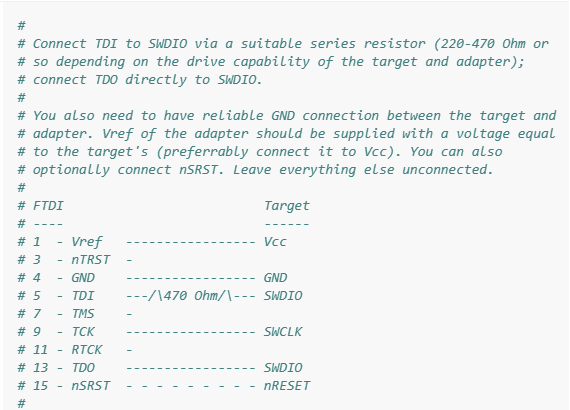
线路连接方式很清楚。FTDI FT2232D芯片侧TDI和TDO连接一个(220~470欧姆的电阻),然后TDO连接到目标板SWDIO信号上, TCK连接目标板SWCLK信号上。
我们从FT2232D的PIN定义看出实际PIN脚部连接如下:
VCC --> VCC (AD0) ADBUS0 (PIN #16) TCK --> SWCLK (AD2) ADBUS2 (PIN #18) TDO --> SWDIO GND --> GND
Debuger Adapter 连接到目标板后,我们可以使用它OPENOCD连接目标板。OPENOCD你可以参考如何构建环境OpenOCD环境基于Window10 Cygwin?
在用OPENOCD在访问目标板之前,我们必须准备两个配置文件,一个是FT2232D Debuger Adapter配置文件,一个是目标板配置文件。您还可以制作配置文件。做两个会更符合OPENOCD的使用。Debuger Adapter一般放在..\scripts\interface\ftdi\目录。目标板的配置文件一般放置在..\scripts\target\目录。
# # Connect TDI to SWDIO via a suitable series resistor (220-470 Ohm or # so depending on the drive capability of the target and adapter); # connect TDO directly to SWDIO. # # You also need to have reliable GND connection between the target and # adapter. Vref of the adapter should be supplied with a voltage equal # to the target's (preferrably connect it to Vcc). You can also # optionally connect nSRST. Leave everything else unconnected. # # FTDI Target # ---- ------ # 1 - Vref ----------------- Vcc # 3 - nTRST - # 4 - GND ----------------- GND # 5 - TDI ---/\470 Ohm/\--- SWDIO # 7 - TMS - # 9 - TCK ----------------- SWCLK # 11 - RTCK - # 13 - TDO ----------------- SWDIO # 15 - nSRST - - - - - - - - - nRESET # # # FTDI FT2232HL # # https://ftdichip.com/products/ft2232hl/ # adapter driver ftdi # select swd interface protocol transport select swd # FT2232D has two USB Serial Converter A/B VendorID (0x0403) DeviceID (0x6010) # USB Serial Converter A ADBUS # USB Serial Converter B ACBUS ftdi_vid_pid 0x0403 0x6010 # ftdi_device_desc description # 指定调试器的描述符。 # ftdi_serial serial-number # 指定调试器SerialNumber。 # ftdi_serial serial-number # 指定调试器SerialNumber。 # ftdi_channel channel # 指定FTDI设备的Channel。对应FT232H来说,只有Channel0(默认),FT2232H/FT4232H是Channel0和Channel1。 adapter speed 1000 # ftdi_layout_init [data] [direction] # 指定FTDIGPIO16初始数据和方向bit数据宽度。 # 参数data中间1表示高电平,0表示低电平,参数direction中1表示输出,0表示输入(注意不同于常规设置) ftdi_layout_init 0x0018 0x05fb # This means: ADBUS(bit7~bit0) # Low output data = 0x18 // 0001 1000 # Low direction = 0xfb // 1111 1011 # High direction = 0x05 // 0000 0101 # 默认情况是JTAG,如果要使用SWD,则需要配置SWD_EN。 ftdi_layout_signal SWD_EN -data 0 # ftdi_layout_signal name [-data|-ndata data_mask] [-input|-ninput input_mask] [-oe|-noe oe_mask] [-alias|-nalias name] # 创建一个名字name的信号。 # [-data|-ndata data_mask] # data_mask:pin mask ndata:invert -data:normal bit # data_mask是对应pin脚的掩码,-ndata表示输入数据反向,-data则不反向。 # [-input|-ninput input_mask] # input_mask:pin mask -input:input pin enable -ninput:input pin disable # input_mask:表示对应pin脚是否输入,-input表示输入,-ninput表示非输入。 # [-oe|-noe oe_mask] # oe_mask:pin mask -oe:output pin enable noe:output pin disable # oe_mask:表示对应pin脚是否输出,-oe表示输出,-noe表示非输出。 # [-alias|-nalias name] # -alias:Normal logic -nalias:Opposite logic # 如果使用-alias(或-nalias),将相同的信号(或数据取反)创建到指定的信号名称。 ftdi_layout_signal nSRST -data 0x0010 # ftdi_set_signal name 0|1|z # 输出信号 # -0:输出低 # -1:输出高 # -z:设置为高阻态 # ftdi_get_signal name # 读取信号 # ftdi_tdo_sample_edge rising|falling # -rising, TCK上升沿采样TDO,默认 # -falling, TCK下降沿采样TDO 在ftdi_ft2232d.cfg文件中的注释已经清楚地介绍了每一个debuger adatper配置命令。
以下是我写的目标板配置文件nxp_s32k3x4.cfg # script for s32k3xx family # # s32k3xx devices support both JTAG and SWD transports. # 以下两份文件是必要的,因为涉及到JTAG 和 SWD 接口通用,即使你由SWD换成了JTAG脚本一样支持 source [find target/swj-dp.tcl] source [find mem_helper.tcl]  # 如果不使用芯片名,s32k3xx为芯片名 if { [info exists CHIPNAME] } {    set _CHIPNAME $CHIPNAME } else {    set _CHIPNAME s32k3xx }  # 设置芯片大小端格式    set _ENDIAN little  # 为加载RAM BIOS ELF文件,设置256KB的RAM并准备清理空间 # Work-area is a space in RAM used for flash pogramming
# By default use 256kB
if { [info exists WORKAREASIZE] } {
   set _WORKAREASIZE $WORKAREASIZE
} else {
   set _WORKAREASIZE 0x40000
}

# 检查芯片的DAP/TAP的ID是否是0x6ba00477, Cortex M7的DAP ID统一为0x6ba00477
#jtag scan chain
if { [info exists CPUTAPID] } {
   set _CPUTAPID $CPUTAPID
} else {
   if { [using_jtag] } {
      # See STM Document RM0385
      # Section 40.6.3 - corresponds to Cortex-M7 with FPU r1p2
      set _CPUTAPID 0x6ba00477
   } {
      set _CPUTAPID 0x6ba02477
   }
}

# 检测_CPUTAPID是不是0x6ba02477,如果是创建芯片的DAP,创建DAP接口后便可以通过DAP访问芯片所有AP接口寄存器。
swj_newdap $_CHIPNAME armv7m -irlen 4 -ircapture 0x1 -irmask 0xf -expected-id $_CPUTAPID
dap create $_CHIPNAME.dap -chain-position $_CHIPNAME.armv7m

if {[using_jtag]} {
   jtag newtap $_CHIPNAME bs -irlen 5
}

global TARGET

set TARGET       $_CHIPNAME.armv7m
set TARGET_MEMAP $_CHIPNAME.memap

# 创建芯片 Target,这个过程中通过DAP接口搜索所有AP。
# 由于NXP S32K344存在多cortex_m 内核互联的MEM AP.会导致target_examine失败。
# 因为我知道S32K344的Cortex M7 core 0的MEM AP为4,所以我指定检索-ap-num 4
target create ${TARGET}.cm7_0    cortex_m -endian $_ENDIAN -dap $_CHIPNAME.dap -ap-num 4 -coreid 0

# 必须init target相关的dap mmw mdw 才能在脚本成功被调用,不然后报错。
init

# 我在ftdi_ft2232d.cfg中,我设定了ADBUS4管脚为目标板的硬件RST
# 硬件复位
ftdi_set_signal nSRST 0
# 延时100ms
adapter srst delay 100
# 硬件解复位
ftdi_set_signal nSRST 1

# 注意:由于S32K344的debug 模式不是默认开启,需要通过DAP访问SDA-AP使能Debug模式
# 如果不使能DAP是无法接入Cortex M7 core 0的MEM AP
# Enable Cortex-M7 Core0 debug request
s32k3xx.dap  apreg 7 0x80 0x300000f0

# 复位Cortex-M7 Core0内部寄存器配置
cortex_m reset_config sysresetreq
cortex_m reset_config vectreset

# 启动调试模式,让Cortex-M7 Core0 halt等待下面得加载命令。
halt

# 为加载RAM BIOS ELF文件,设置256KB的RAM空间并且准备清零
${TARGET}.cm7_0 configure -work-area-phys 0x20400000 -work-area-size $_WORKAREASIZE -work-area-backup 0
# 这里是加载我特意准备为实现烧写功能得RAM ELF文件。该RAM ELF是通过调试串口UART实现FLASH文件烧写。
# 注意在load_image之前必须得把target halt。
load_image D:/Work_Data/my_projects/S32K344_EVB/xpack-openocd-0.10.0-15-win32-x64/xpack-openocd-0.10.0-15/bin/Dio_example_DS.elf
# 这里我RAM ELF得起始地址是0x20400010,这里指定从0x20400010恢复。resume 是把PC指针指向0x20400010,释放了debug 模式。
resume 0x20400010

#下面是Target事件,其实它得实现方式类似于我们在代码里函数钩子。
# 因为每个芯片得Target Events处理是不一样的。这些事件需要做特殊处理

# 由于S32K3芯片的特殊性,如果不使能DAP是无法接入Cortex M7 core 0的MEM AP。
# 所以我增加了SDA AP使能在examine-start,确保在target_examine之前物理通路是通的。
${TARGET}.cm7_0 configure -event examine-start {
	# Enable Cortex-M7 Core0 debug request
	s32k3xx.dap  apreg 7 0x80 0x300000f0
}

# 为了在Telnel或者gdb调试过程中发起reset init/halt
${TARGET}.cm7_0 configure -event reset-init {
	# Keep the old DEMCR value.
	set old [mrw 0xE000EDFC]
    mww 0xE000ED08 0x20430000
	# Enable vector catch on reset.
	mww 0xE000EDFC 0x01000001

	# Issue local reset via AIRCR.
	mww 0xE000ED0C 0x05FA0001

	# Restore old DEMCR value.
	mww 0xE000EDFC $old

	cortex_m reset_config sysresetreq
	cortex_m reset_config vectreset

	mww 0x402DC140 0x00000001 1
	mww 0x402DC144 0x00000001 1

	mww 0x402DC134 0x0000F7DF 1
	mww 0x402DC100 0x00000001 1
	mww 0x402DC104 0x00000001 1
	mww 0x402DC000 0x00005AF0 1
	mww 0x402DC000 0x0000A50F 1

	mww 0x402DC330 0xB1E0FFF8 1
	mww 0x402DC334 0x812AA407 1
	mww 0x402DC338 0xBBF3FE7E 1
	mww 0x402DC33C 0x00000141 1
	mww 0x402DC300 0x00000001 1
	mww 0x402DC304 0x00000001 1
	mww 0x402DC000 0x00005AF0 1
	mww 0x402DC000 0x0000A50F 1

	mww 0x402DC530 0x29FFFFF0 1
	mww 0x402DC534 0xC48987F9 1
	mww 0x402DC500 0x00000001 1
	mww 0x402DC504 0x00000001 1
	mww 0x402DC000 0x00005AF0 1
	mww 0x402DC000 0x0000A50F 1

	# Disable WATCHDOG
	mwb 0x40280003 0x80 1
	mww 0x40210020 0x00400000 1
	mww 0x40210024 0x03030000 1
	mww 0x40210028 0x00050000 1
	mww 0x4021002C 0x00000000 1

	mww 0x40210030 0x20400000 1
	mww 0x40210034 0x00080008 1
	mww 0x40210038 0xFFFB0000 1
	mww 0x4021003C 0x00000001 1
}
在运行OPENOCD之前必须得需要安装SysProgs USB Driver Tool。 处理用于OpenOCD的USB驱动程序可能会很麻烦,尤其是在Windows上。 SysProgs USB驱动程序工具简化了很多操作: •从 https://visualgdb.com/UsbDriverTool 下载该工具并安装(实际上,它只是将文件解压缩到您选择的文件夹中) •运行工具
看到USB Serial Converter A/B Vendor ID 0403 Device ID 6010的两个USB设备。
选择USB Serial Converter A,将它的USB驱动安装成WinUSB.
把ftdi_ft2232d.cfg和nxp_s32k3x4.cfg拷贝到你想运行的目录。我这里的目录是D:\cygwin64\home\$user
$ openocd.exe  -f ftdi_ft2232d.cfg -f nxp_s32k3x4.cfg
Open On-Chip Debugger 0.11.0 (2021-03-23-12:47)
Licensed under GNU GPL v2
For bug reports, read
        http://openocd.org/doc/doxygen/bugs.html
Info : FTDI SWD mode enabled
Error: libusb_open() failed with LIBUSB_ERROR_NOT_SUPPORTED  #忽略这两个错误
Error: libusb_open() failed with LIBUSB_ERROR_NOT_SUPPORTED
Info : clock speed 1000 kHz
Info : SWD DPIDR 0x6ba02477
Info : s32k3xx.armv7m.cm7_0: hardware has 8 breakpoints, 4 watchpoints
Info : starting gdb server for s32k3xx.armv7m.cm7_0 on 3333
Info : Listening on port 3333 for gdb connections
Info : Listening on port 6666 for tcl connections
Info : Listening on port 4444 for telnet connections
OPENOCD默认调试信息等级是2,如果你想看到更多的调试信息命令如下:
$ openocd.exe  -f ftdi_ft2232d.cfg -f nxp_s32k3x4.cfg -d3
Open On-Chip Debugger 0.11.0 (2021-03-23-12:47)
Licensed under GNU GPL v2
For bug reports, read
        http://openocd.org/doc/doxygen/bugs.html
User : 13 3 options.c:63 configuration_output_handler(): debug_level: 3
User : 14 5 options.c:63 configuration_output_handler():
Debug: 15 7 options.c:244 add_default_dirs(): bindir=/usr/local/bin
Debug: 16 8 options.c:245 add_default_dirs(): pkgdatadir=/usr/local/share/openocd
Debug: 17 10 options.c:246 add_default_dirs(): exepath=/usr/local/bin
Debug: 18 12 options.c:247 add_default_dirs(): bin2data=../share/openocd
Debug: 19 14 configuration.c:42 add_script_search_dir(): adding C:/Users/wezhu/AppData/Roaming/OpenOCD
Debug: 20 16 configuration.c:42 add_script_search_dir(): adding /home/WeZhu/.config/openocd
Debug: 21 18 configuration.c:42 add_script_search_dir(): adding /home/WeZhu/.openocd
Debug: 22 20 configuration.c:42 add_script_search_dir(): adding /usr/local/bin/../share/openocd/site
Debug: 23 23 configuration.c:42 add_script_search_dir(): adding /usr/local/bin/../share/openocd/scripts
Debug: 24 25 configuration.c:97 find_file(): found ftdi_ft2232d.cfg
Debug: 25 26 command.c:146 script_debug(): command - adapter driver ftdi
Debug: 27 28 command.c:146 script_debug(): command - transport select swd
Info : 28 30 ftdi.c:1035 ftdi_swd_init(): FTDI SWD mode enabled
Debug: 29 31 command.c:146 script_debug(): command - ftdi_vid_pid 0x0403 0x6010
Debug: 31 33 command.c:146 script_debug(): command - adapter speed 1000
Debug: 33 35 core.c:1822 jtag_config_khz(): handle jtag khz
Debug: 34 37 core.c:1785 adapter_khz_to_speed(): convert khz to interface specific speed value
Debug: 35 39 core.c:1785 adapter_khz_to_speed(): convert khz to interface specific speed value
Debug: 36 41 command.c:146 script_debug(): command - ftdi_layout_init 0x0018 0x05fb
Debug: 38 42 command.c:146 script_debug(): command - ftdi_layout_signal SWD_EN -data 0
Debug: 40 44 command.c:146 script_debug(): command - ftdi_layout_signal nSRST -data 0x0010
……
……
Debug: 206 1311 ftdi.c:648 ftdi_initialize(): ftdi interface using shortest path jtag state transitions
Debug: 207 1363 mpsse.c:422 mpsse_purge(): -
Debug: 208 1366 mpsse.c:703 mpsse_loopback_config(): off
Debug: 209 1369 mpsse.c:748 mpsse_set_frequency(): target 1000000 Hz
Debug: 210 1372 mpsse.c:740 mpsse_rtck_config(): off
Debug: 211 1376 mpsse.c:729 mpsse_divide_by_5_config(): off
Debug: 212 1379 mpsse.c:709 mpsse_set_divisor(): 29
Debug: 213 1388 mpsse.c:772 mpsse_set_frequency(): actually 1000000 Hz
Debug: 214 1395 core.c:1785 adapter_khz_to_speed(): convert khz to interface specific speed value
Debug: 215 1399 core.c:1789 adapter_khz_to_speed(): have interface set up
Debug: 216 1406 mpsse.c:748 mpsse_set_frequency(): target 1000000 Hz
Debug: 217 1410 mpsse.c:740 mpsse_rtck_config(): off
Debug: 218 1418 mpsse.c:729 mpsse_divide_by_5_config(): off
Debug: 219 1430 mpsse.c:709 mpsse_set_divisor(): 29
Debug: 220 1432 mpsse.c:772 mpsse_set_frequency(): actually 1000000 Hz
Debug: 221 1441 core.c:1785 adapter_khz_to_speed(): convert khz to interface specific speed value
Debug: 222 1446 core.c:1789 adapter_khz_to_speed(): have interface set up
Info : 223 1452 core.c:1565 adapter_init(): clock speed 1000 kHz
Debug: 224 1462 openocd.c:157 handle_init_command(): Debug Adapter init complete
Debug: 225 1466 command.c:146 script_debug(): command - transport init
Debug: 227 1475 transport.c:239 handle_transport_init(): handle_transport_init
Debug: 228 1480 command.c:146 script_debug(): command - dap init
Debug: 230 1486 arm_dap.c:106 dap_init_all(): Initializing all DAPs ...
Debug: 231 1497 ftdi.c:1209 ftdi_swd_switch_seq(): JTAG-to-SWD
Info : 233 1500 adi_v5_swd.c:136 swd_connect(): SWD DPIDR 0x6ba02477
Debug: 234 1510 arm_adi_v5.c:653 dap_dp_init(): s32k3xx.dap
Debug: 235 1514 arm_adi_v5.c:698 dap_dp_init(): DAP: wait CDBGPWRUPACK
Debug: 236 1521 arm_adi_v5.h:506 dap_dp_poll_register(): DAP: poll 4, mask 0x20000000, value 0x20000000
Debug: 237 1532 arm_adi_v5.c:706 dap_dp_init(): DAP: wait CSYSPWRUPACK
Debug: 238 1538 arm_adi_v5.h:506 dap_dp_poll_register(): DAP: poll 4, mask 0x80000000, value 0x80000000
Debug: 239 1552 openocd.c:174 handle_init_command(): Examining targets...
Debug: 240 1563 target.c:1644 target_call_event_callbacks(): target event 19 (examine-start) for core s32k3xx.armv7m.cm7_0
Debug: 241 1569 arm_adi_v5.c:776 mem_ap_init(): MEM_AP Packed Transfers: enabled
Debug: 242 1576 arm_adi_v5.c:787 mem_ap_init(): MEM_AP CFG: large data 0, long address 0, big-endian 0
Debug: 243 1584 target.c:2406 target_read_u32(): address: 0xe000ed00, value: 0x411fc272
Debug: 244 1587 cortex_m.c:2194 cortex_m_examine(): Cortex-M7 r1p2 processor detected
Debug: 245 1596 cortex_m.c:2206 cortex_m_examine(): cpuid: 0x411fc272
Debug: 246 1600 target.c:2406 target_read_u32(): address: 0xe000ef40, value: 0x10110021
Debug: 247 1611 target.c:2406 target_read_u32(): address: 0xe000ef44, value: 0x11000011
Debug: 248 1619 cortex_m.c:2226 cortex_m_examine(): Cortex-M7 floating point feature FPv5_SP found
Debug: 249 1629 target.c:2406 target_read_u32(): address: 0xe000edf0, value: 0x01010001
Debug: 250 1633 target.c:2494 target_write_u32(): address: 0xe000edfc, value: 0x01000000
Debug: 251 1643 target.c:2406 target_read_u32(): address: 0xe0002000, value: 0x10000081
Debug: 252 1646 target.c:2494 target_write_u32(): address: 0xe0002008, value: 0x00000000
Debug: 253 1654 target.c:2494 target_write_u32(): address: 0xe000200c, value: 0x00000000
Debug: 254 1664 target.c:2494 target_write_u32(): address: 0xe0002010, value: 0x00000000
Debug: 255 1669 target.c:2494 target_write_u32(): address: 0xe0002014, value: 0x00000000
Debug: 256 1678 target.c:2494 target_write_u32(): address: 0xe0002018, value: 0x00000000
Debug: 257 1683 target.c:2494 target_write_u32(): address: 0xe000201c, value: 0x00000000
Debug: 258 1690 target.c:2494 target_write_u32(): address: 0xe0002020, value: 0x00000000
Debug: 259 1694 target.c:2494 target_write_u32(): address: 0xe0002024, value: 0x00000000
Debug: 260 1700 cortex_m.c:2308 cortex_m_examine(): FPB fpcr 0x10000081, numcode 8, numlit 0
Debug: 261 1708 target.c:2406 target_read_u32(): address: 0xe0001000, value: 0x40000000
Debug: 262 1712 cortex_m.c:2024 cortex_m_dwt_setup(): DWT_CTRL: 0x40000000
Debug: 263 1719 target.c:2406 target_read_u32(): address: 0xe0001fbc, value: 0x00000000
Debug: 264 1730 cortex_m.c:2031 cortex_m_dwt_setup(): DWT_DEVARCH: 0x0
Debug: 265 1733 target.c:2494 target_write_u32(): address: 0xe0001028, value: 0x00000000
Debug: 266 1743 target.c:2494 target_write_u32(): address: 0xe0001038, value: 0x00000000
Debug: 267 1751 target.c:2494 target_write_u32(): address: 0xe0001048, value: 0x00000000
Debug: 268 1763 target.c:2494 target_write_u32(): address: 0xe0001058, value: 0x00000000
Debug: 269 1767 cortex_m.c:2078 cortex_m_dwt_setup(): DWT dwtcr 0x40000000, comp 4, watch/trigger
Info : 270 1776 cortex_m.c:2318 cortex_m_examine(): s32k3xx.armv7m.cm7_0: hardware has 8 breakpoints, 4 watchpoints
Debug: 271 1784 target.c:1644 target_call_event_callbacks(): target event 21 (examine-end) for core s32k3xx.armv7m.cm7_0
Debug: 272 1799 command.c:146 script_debug(): command - flash init
Debug: 274 1806 tcl.c:1324 handle_flash_init_command(): Initializing flash devices...
Debug: 275 1818 command.c:146 script_debug(): command - nand init
Debug: 277 1822 tcl.c:498 handle_nand_init_command(): Initializing NAND devices...
Debug: 278 1827 command.c:146 script_debug(): command - pld init
Debug: 280 1832 pld.c:206 handle_pld_init_command(): Initializing PLDs...
Info : 281 1841 gdb_server.c:3503 gdb_target_start(): starting gdb server for s32k3xx.armv7m.cm7_0 on 3333
Info : 282 1850 server.c:310 add_service(): Listening on port 3333 for gdb connections
Debug: 283 1858 command.c:146 script_debug(): command - s32k3xx.dap apreg 7 0x80 0x300000f0
Info : 285 1864 server.c:310 add_service(): Listening on port 6666 for tcl connections
Info : 286 1870 server.c:310 add_service(): Listening on port 4444 for telnet connections
Debug: 287 1879 command.c:146 script_debug(): command - init
你几乎可以看到每条配置文件中每条命令的响应,可以帮助你理解整个接入流程。
下面我可以通过Telent 端口4444登录到目标板内核Cortex-M7内部查看响应DAP的信息。 Windows10系统自带Telnet客户端安装。由于我的系统是英文版的,所以步骤我这里就直接用英文了:
1. Click Start.
2. Select Control Panel.
3. Choose Programs and Features.
4. Click Turn Windows features on or off.
5. Select the Telnet Client option.
Click OK. A dialog box appears to confirm installation. The telnet command should now be available.
安装完Telnet客户端后,我们直接在运行里敲cmd进入windows 命令行. 进入到命令行后执行telnet localhost 4444
Open On-Chip Debugger
> dap
adapter
  adapter assert |deassert [srst|trst [assert|deassert srst|trst]]
  adapter deassert |assert [srst|trst [deassert|assert srst|trst]]
  adapter driver driver_name
  adapter list
  adapter name
  adapter speed [khz]
  adapter srst
    adapter srst delay [milliseconds]
    adapter srst pulse_width [milliseconds]
  adapter transports transport ...
  adapter usb
    adapter usb location [<bus>-port[.port]...]
dap
  dap create name '-chain-position' name
  dap info [ap_num]
  dap init
  dap names
reset_config [none|trst_only|srst_only|trst_and_srst]
          [srst_pulls_trst|trst_pulls_srst|combined|separate]
          [srst_gates_jtag|srst_nogate] [trst_push_pull|trst_open_drain]
          [srst_push_pull|srst_open_drain]
          [connect_deassert_srst|connect_assert_srst]
s32k3xx.dap
  s32k3xx.dap apcsw [value [mask]]
  s32k3xx.dap apid [ap_num]
  s32k3xx.dap apreg ap_num reg [value]
  s32k3xx.dap apsel [ap_num]
  s32k3xx.dap baseaddr [ap_num]
  s32k3xx.dap dpreg reg [value]
  s32k3xx.dap info [ap_num]
  s32k3xx.dap memaccess [cycles]
  s32k3xx.dap ti_be_32_quirks [enable]
  swd newdap
dap: command requires more arguments
通过dap info [ap_num]可以查看到到底有多少个AP连接到SWD上
> dap info 1
SWD DPIDR 0x6ba02477
AP ID register 0x54770002
        Type is MEM-AP APB
MEM-AP BASE 0x80000003
        Valid ROM table present
                Component base address 0x80000000
                Peripheral ID 0x000008e995
                Designer is 0x08e, Freescale (Motorola)
                Part is 0x995, Unrecognized
                Component class is 0x1, ROM table
                MEMTYPE system memory not present: dedicated debug bus
        ROMTABLE[0x0] = 0x1003
                Component base address 0x80001000
                Peripheral ID 0x04003bb908
                Designer is 0x4bb, ARM Ltd
                Part is 0x908, CoreSight CSTF (Trace Funnel)
                Component class is 0x9, CoreSight component
                Type is 0x12, Trace Link, Funnel, router
        ROMTABLE[0x4] = 0x2003
                Component base address 0x80002000
                Peripheral ID 0x04003bb908
                Designer is 0x4bb, ARM Ltd
                Part is 0x908, CoreSight CSTF (Trace Funnel)
                Component class is 0x9, CoreSight component
                Type is 0x12, Trace Link, Funnel, router
        ROMTABLE[0x8] = 0x3003
                Component base address 0x80003000
                Peripheral ID 0x04003bb908
                Designer is 0x4bb, ARM Ltd
                Part is 0x908, CoreSight CSTF (Trace Funnel)
                Component class is 0x9, CoreSight component
                Type is 0x12, Trace Link, Funnel, router
        ROMTABLE[0xc] = 0x4003
                Component base address 0x80004000
                Peripheral ID 0x04001bb961
                Designer is 0x4bb, ARM Ltd
                Part is 0x961, CoreSight TMC (Trace Memory Controller)
                Component class is 0x9, CoreSight component
                Type is 0x32, Trace Link, FIFO, buffer
        ROMTABLE[0x10] = 0x5003
                Component base address 0x80005000
                Peripheral ID 0x04001bb961
                Designer is 0x4bb, ARM Ltd
                Part is 0x961, CoreSight TMC (Trace Memory Controller)
                Component class is 0x9, CoreSight component
                Type is 0x32, Trace Link, FIFO, buffer
        ROMTABLE[0x14] = 0x6003
                Component base address 0x80006000
                Peripheral ID 0x04001bb961
                Designer is 0x4bb, ARM Ltd
                Part is 0x961, CoreSight TMC (Trace Memory Controller)
                Component class is 0x9, CoreSight component
                Type is 0x32, Trace Link, FIFO, buffer
        ROMTABLE[0x18] = 0x7003
                Component base address 0x80007000
                Peripheral ID 0x04001bb961
                Designer is 0x4bb, ARM Ltd
                Part is 0x961, CoreSight TMC (Trace Memory Controller)
                Component class is 0x9, CoreSight component
                Type is 0x32, Trace Link, FIFO, buffer
        ROMTABLE[0x1c] = 0x8003
                Component base address 0x80008000
                Peripheral ID 0x04004bb917
                Designer is 0x4bb, ARM Ltd
                Part is 0x917, CoreSight HTM (AHB Trace Macrocell)
                Component class is 0x9, CoreSight component
                Type is 0x43, Trace Source, Bus
        ROMTABLE[0x20] = 0x9003
                Component base address 0x80009000
                Peripheral ID 0x04005bb906
                Designer is 0x4bb, ARM Ltd
                Part is 0x906, CoreSight CTI (Cross Trigger)
                Component class is 0x9, CoreSight component
                Type is 0x14, Debug Control, Trigger Matrix
        ROMTABLE[0x24] = 0xa003
                Component base address 0x8000a000
                Can't read component, the corresponding core might be turned off
> dap info 2
AP ID register 0x84770001
        Type is MEM-AP AHB3
MEM-AP BASE 0xf0000003
        Valid ROM table present
                Component base address 0xf0000000
                Can't read component, the corresponding core might be turned off

> dap info 4
AP ID register 0x84770001
        Type is MEM-AP AHB3
MEM-AP BASE 0xe00fe003
        Valid ROM table present
                Component base address 0xe00fe000
                Peripheral ID 0x04000bb4c8
                Designer is 0x4bb, ARM Ltd
                Part is 0x4c8, Cortex-M7 ROM (ROM Table)
                Component class is 0x1, ROM table
                MEMTYPE system memory present on bus
        ROMTABLE[0x0] = 0x1003
                Component base address 0xe00ff000
                Peripheral ID 0x04000bb4c7
                Designer is 0x4bb, ARM Ltd
                Part is 0x4c7, Cortex-M7 PPB ROM (Private Peripheral Bus ROM Table)
                Component class is 0x1, ROM table
                MEMTYPE system memory present on bus
        [L01] ROMTABLE[0x0] = 0xfff0f003
                Component base address 0xe000e000
                Peripheral ID 0x04000bb00c
                Designer is 0x4bb, ARM Ltd
                Part is 0xc, Cortex-M4 SCS (System Control Space)
                Component class is 0xe, Generic IP component
        [L01] ROMTABLE[0x4] = 0xfff02003
                Component base address 0xe0001000
                Peripheral ID 0x04000bb002
                Designer is 0x4bb, ARM Ltd
                Part is 0x2, Cortex-M3 DWT (Data Watchpoint and Trace)
                Component class is 0xe, Generic IP component
        [L01] ROMTABLE[0x8] = 0xfff03003
                Component base address 0xe0002000
                Peripheral ID 0x04000bb00e
                Designer is 0x4bb, ARM Ltd
                Part is 0xe, Cortex-M7 FPB (Flash Patch and Breakpoint)
                Component class is 0xe, Generic IP component
        [L01] ROMTABLE[0xc] = 0xfff01003
                Component base address 0xe0000000
                Peripheral ID 0x04000bb001
                Designer is 0x4bb, ARM Ltd
                Part is 0x1, Cortex-M3 ITM (Instrumentation Trace Module)
                Component class is 0xe, Generic IP component
        [L01] ROMTABLE[0x10] = 0xfff41002
                Component not present
        [L01] ROMTABLE[0x14] = 0xfff42002
                Component not present
        [L01] ROMTABLE[0x18] = 0x0
        [L01]   End of ROM table
        ROMTABLE[0x4] = 0xfff43003
                Component base address 0xe0041000
                Peripheral ID 0x04001bb975
                Designer is 0x4bb, ARM Ltd
                Part is 0x975, Cortex-M7 ETM (Embedded Trace)
                Component class is 0x9, CoreSight component
                Type is 0x13, Trace Source, Processor
        ROMTABLE[0x8] = 0xfff44003
                Component base address 0xe0042000
                Peripheral ID 0x04004bb906
                Designer is 0x4bb, ARM Ltd
                Part is 0x906, CoreSight CTI (Cross Trigger)
                Component class is 0x9, CoreSight component
                Type is 0x14, Debug Control, Trigger Matrix
        ROMTABLE[0xc] = 0x1ff02002
                Component not present
        ROMTABLE[0x10] = 0x0
                End of ROM table

> dap info 6
AP ID register 0x001c0030
        Unknown AP type

> dap info 7
AP ID register 0x001c0040
        Unknown AP type
基本看到对应关系如下:
dap info 显示的内容我就不再展开了,里面的对应内容大家可以在Arm CoreSight SoC-400 Technical Reference Manual , CoreSight Components Technical Reference Manual ,ARM® Debug Interface Architecture Specification ADIv5.0 to ADIv5.2 和 Arm Cortex-M7 Processor Technical Reference Manual 找到对应关系和解释。
大家还可以通过 s32k3xx.dap apreg ap_num reg [value] 访问所有可以见到的AP的寄存器内容。
我们选择AP4 MEM-AP AHB AP 参考文档ARM® Debug Interface Architecture Specification ADIv5.0 to ADIv5.2 章节 7.The Memory Access Port (MEM-AP) Table 7-6 Summary of Memory Access Port (MEM-AP) registers
读取0xFC IDR, Identification Register
> s32k3xx.dap apreg 4 0xFC
0x84770001
读取0xF8 BASE, Debug Base Address register
> s32k3xx.dap apreg 4 0xF8
0xe00fe003
如果你想获取Cortex M7内部寄存器的访问,
> s32k3xx.armv7m.cm7_0    #这个是我们在目标板配置文件中给Target的命名
s32k3xx.armv7m.cm7_0
  s32k3xx.armv7m.cm7_0 arm
    s32k3xx.armv7m.cm7_0 arm core_state ['arm'|'thumb']
    s32k3xx.armv7m.cm7_0 arm disassemble address [count ['thumb']]
    s32k3xx.armv7m.cm7_0 arm mcr cpnum op1 CRn CRm op2 value
    s32k3xx.armv7m.cm7_0 arm mrc cpnum op1 CRn CRm op2
    s32k3xx.armv7m.cm7_0 arm reg
    s32k3xx.armv7m.cm7_0 arm semihosting ['enable'|'disable']
    s32k3xx.armv7m.cm7_0 arm semihosting_cmdline arguments
    s32k3xx.armv7m.cm7_0 arm semihosting_fileio ['enable'|'disable']
    s32k3xx.armv7m.cm7_0 arm semihosting_resexit ['enable'|'disable']
  s32k3xx.armv7m.cm7_0 arp_examine ['allow-defer']
  s32k3xx.armv7m.cm7_0 arp_halt
  s32k3xx.armv7m.cm7_0 arp_halt_gdb
  s32k3xx.armv7m.cm7_0 arp_poll
  s32k3xx.armv7m.cm7_0 arp_reset
  s32k3xx.armv7m.cm7_0 arp_waitstate
  s32k3xx.armv7m.cm7_0 array2mem arrayname bitwidth address count
  s32k3xx.armv7m.cm7_0 cget target_attribute
  s32k3xx.armv7m.cm7_0 configure [target_attribute ...]
  s32k3xx.armv7m.cm7_0 cortex_m
    s32k3xx.armv7m.cm7_0 cortex_m maskisr ['auto'|'on'|'off'|'steponly']
    s32k3xx.armv7m.cm7_0 cortex_m reset_config ['sysresetreq'|'vectreset']
    s32k3xx.armv7m.cm7_0 cortex_m vector_catch ['all'|'none'|('bus_err'|'chk_err'|...)*]
  s32k3xx.armv7m.cm7_0 curstate
  s32k3xx.armv7m.cm7_0 eventlist
  s32k3xx.armv7m.cm7_0 examine_deferred
  s32k3xx.armv7m.cm7_0 invoke-event event_name
  s32k3xx.armv7m.cm7_0 itm
    s32k3xx.armv7m.cm7_0 itm port <port> (0|1|on|off)
    s32k3xx.armv7m.cm7_0 itm ports (0|1|on|off)
  s32k3xx.armv7m.cm7_0 mdb address [count]
  s32k3xx.armv7m.cm7_0 mdd address [count]
  s32k3xx.armv7m.cm7_0 mdh address [count]
  s32k3xx.armv7m.cm7_0 mdw address [count]            #双字节读取
  s32k3xx.armv7m.cm7_0 mem2array arrayname bitwidth address count
  s32k3xx.armv7m.cm7_0 mwb address data [count]
  s32k3xx.armv7m.cm7_0 mwd address data [count]
  s32k3xx.armv7m.cm7_0 mwh address data [count]
  s32k3xx.armv7m.cm7_0 mww address data [count]        #双字节写入
  s32k3xx.armv7m.cm7_0 rtt
    s32k3xx.armv7m.cm7_0 rtt channellist
    s32k3xx.armv7m.cm7_0 rtt channels
    s32k3xx.armv7m.cm7_0 rtt polling_interval [interval]
    s32k3xx.armv7m.cm7_0 rtt setup <address> <size> <ID>
    s32k3xx.armv7m.cm7_0 rtt start
    s32k3xx.armv7m.cm7_0 rtt stop
  s32k3xx.armv7m.cm7_0 tpiu
    s32k3xx.armv7m.cm7_0 tpiu config (disable | ((external | internal (<filename> | <:port> | -)) (sync <port
              width> | ((manchester | uart) <formatter enable>))
              <TRACECLKIN freq> [<trace freq>]))
  s32k3xx.armv7m.cm7_0 was_examined
s32k3xx.armv7m.cm7_0: command requires more arguments
或者你直接使用mww 和mdw 命令也可以。因为OpenOCD默认使用 s32k3xx.armv7m.cm7_0 mww 和 s32k3xx.armv7m.cm7_0 mdw替换。
举例:向寄存器0x402DC000 ,写入0x0000A50F
> mww 0x402DC000 0x0000A50F 1读取寄存器0x402DC000
> mdw 0x402DC000 1
0x402dc000: 00005af0
我们可以使用arm-none-eabi-gdb 工具进行断点调试。GDB登录端口3333
arm-none-eabi-gdb 软件资源很多Windows10的资源如下:
- xPack GNU Arm Embedded GCC v10.2.1-1.1 released
- gcc-arm-none-eabi-10-2020-q4-major-win32.exe
D:\Program Files (x86)\GNU Arm Embedded Toolchain\10 2020-q4-major\bin>arm-none-eabi-gdb.exe D:\Work_Data\my_projects\S32K344_EVB\xpack-openocd-0.10.0-15-win32-x64\xpack-openocd-0.10.0-15\bin\Dio_example_DS.elf
D:\Program Files (x86)\GNU Arm Embedded Toolchain\10 2020-q4-major\bin\arm-none-eabi-gdb.exe: warning: Couldn't determine a path for the index cache directory.
GNU gdb (GNU Arm Embedded Toolchain 10-2020-q4-major) 10.1.90.20201028-git
Copyright (C) 2020 Free Software Foundation, Inc.
License GPLv3+: GNU GPL version 3 or later <http://gnu.org/licenses/gpl.html>
This is free software: you are free to change and redistribute it.
There is NO WARRANTY, to the extent permitted by law.
Type "show copying" and "show warranty" for details.
This GDB was configured as "--host=i686-w64-mingw32 --target=arm-none-eabi".
Type "show configuration" for configuration details.
For bug reporting instructions, please see:
<https://www.gnu.org/software/gdb/bugs/>.
Find the GDB manual and other documentation resources online at:
    <http://www.gnu.org/software/gdb/documentation/>.

For help, type "help".
Type "apropos word" to search for commands related to "word"...
Reading symbols from D:\Work_Data\my_projects\S32K344_EVB\xpack-openocd-0.10.0-15-win32-x64\xpack-openocd-0.10.0-15\bin\Dio_example_DS.elf...
(gdb) target remote 127.0.0.1:3333
Remote debugging using 127.0.0.1:3333
main () at ../src/main.c:74
74                      DelayCount++;
(gdb) bt
#0  main () at ../src/main.c:74
(gdb) b main
Breakpoint 1 at 0x204002a0: file ../src/main.c, line 55.
(gdb) c
Continuing.

Program received signal SIGINT, Interrupt.
0x204002d8 in main () at ../src/main.c:74
74                      DelayCount++;
(gdb) bt
#0  0x204002d8 in main () at ../src/main.c:74
(gdb) list
69                  /* Dio_WriteChannel(DioConf_DioChannel_Digital_Output_LED_D78, STD_LOW); */
70                  Siul2_Dio_Ip_WritePin(PTB_L_HALF, LED_PIN_PIN, 0U);
71                  /*delay*/
72                  while(DelayCount<10000)
73                  {
74                      DelayCount++;
75                  }
76                  DelayCount = 0;
77          }
78
(gdb) print
The history is empty.
(gdb) print DelayCount
$1 = 0
(gdb) set step-mode
(gdb) si
72                  while(DelayCount<10000)
(gdb) si
0x204002ce      72                  while(DelayCount<10000)
(gdb) si
74                      DelayCount++;
(gdb) c
Continuing.

Program received signal SIGINT, Interrupt.
main () at ../src/main.c:74
74                      DelayCount++;
(gdb) list
69                  /* Dio_WriteChannel(DioConf_DioChannel_Digital_Output_LED_D78, STD_LOW); */
70                  Siul2_Dio_Ip_WritePin(PTB_L_HALF, LED_PIN_PIN, 0U);
71                  /*delay*/
72                  while(DelayCount<10000)
73                  {
74                      DelayCount++;
75                  }
76                  DelayCount = 0;
77          }
78
(gdb)
GDB的命令大家可以看宋宝华的Linux gdb调试器用法全面解析和GDB GUI 工具Eclipse使用方法在如何结合Eclipse+OpenOCD+arm-none-eabi-gdb实现可视化在线调试ARM Cortex M7内核?文章中介绍。